In order to increase the measurable range (dynamic range) of the instrument, most measuring instruments are set with multiple ranges to meet the needs of different sizes of signals under different conditions. What happens when using a large range test small signal? Many people's answers will increase the error, but often it is not the reason. Today we will take you to discuss the impact and reasons of such use.
Many people think that the range of large-scale measurable measurement is large, and the size signals can be balanced. Therefore, in many cases, the larger range is preferred for measurement, or the selection is not careful, the default setting is directly set, and the value measured by the instrument when used. Still showing up properly, it seems that the value seems to be accurate. So what is the problem with this use? Let's take a power analyzer as an example.
Precision algorithm decryptionFigure 1 shows the measurement accuracy of the 5A power board of the Zhiyuan electronic PA8000 and PA5000 power analyzer. Let us take this as an example. Among the given accuracy values, the accuracy index of the instrument is marked as “% reading +% rangeâ€, and most measuring equipment is also marked as such. For the frequency range of 45-66 Hz, the accuracy of PA8000 is “0.01%+ 0.03%", PA5000 accuracy is 0.10% + 0.05%, which means that when using 800V range to measure 800V signal, the worst case PA8000 error is 0.01% * 800V + 0.03% * 1000V = 0.38V, PA5000 is 1.3V, The error for a 800V signal is minimal. However, if the 10V signal is measured using the 1000V range, the PA8000 maximum error is 0.301V, and the PA5000 will reach 0.51V. This error is relatively large compared to the 10V signal. For the user, the error between the measured value and the actual value is considered, but for the measuring instrument, the inherent error in a large range will significantly increase the error when measuring the small signal, which may bring the user I hope to see the results.
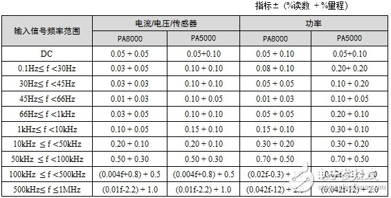
Figure 1 Zhiyuan PA8000/PA5000 Power Analyzer 5A Power Board Accuracy Table
ADC quantization error impactThe reason for this is first caused by the quantization error generated by the ADC inside the measuring device. It is assumed that the measuring device contains an 11-bit ADC. The ADC has 211=2048 effective bits, which is in the range of 1000V (peak-to-peak). Considering the maximum ±1000V input with a total of 2048 effective bits, the ADC will pulsate a minimum unit of 1LSB per beat due to the inevitable noise, resulting in a quantization error of approximately 2000V/2048≈1V. If the range is used to measure a signal such as 10.3V, it is clear that the minimum resolution of a single ADC sample cannot recognize a scale of 0.3V (0.3V in the middle of the two scales in the quantization diagram of Figure 2). Of course, it cannot be measured. The correct value. If the peak value of random noise is greater than 1LSB, the average number of samples can be increased to increase the effective number of bits in the measurement system, but such factors are outside the scope of our consideration.
In this case, it seems that high-digit ADCs can significantly reduce quantization errors, but unfortunately high-order and high-sampling rates are a contradiction because high bandwidth leads to higher noise, while at the same time in existing ADC fabrication processes and architectures. Under the limitation, it is difficult for a high sampling rate ADC to achieve a high effective number of bits at the same time. If our PA8000 and PA5000 want to provide a sampling rate of 2Mbps at a bandwidth of 5MHz, it will be difficult to increase the effective number of bits to more than 18 bits under such a high bandwidth. Therefore, our PA8000 uses an 18-bit, 2Mbps sampling rate ADC. To reduce the quantization error.
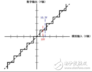
Figure 2 Quantization diagram
Noise and offset effects of front-end analog circuitsAnother problem that cannot be ignored is the influence of noise, offset and gain error caused by the analog circuit itself. The simplified voltage measurement circuit shown in Figure 3, the first picture is the measurement path of 1000V range, the maximum input voltage is 1000V. The attenuation circuit outputs 1V voltage, the amplification circuit does not amplify, and the voltage is fed to the ADC for sampling. If the attenuation circuit can only output 0.01V when inputting 10V, firstly, such a small signal superimposed noise will have a great impact on the signal itself, and secondly due to the offset of the amplifier circuit (op amp) and the gain error, even if only Both 0.1mV offset and gain error can cause large errors in the effective signal of 0.01V. These errors are calibrated before the instrument leaves the factory to eliminate the inherent deviations, but these values ​​will change due to temperature and aging during use. A certain amount of margin will be left to ensure the instrument's accuracy specifications. It is within the guaranteed accuracy, but the effect of temperature and aging when using a large number of measurements to measure small signals will not be guaranteed.
When measuring small signals, the circuit shown in the second picture of Figure 3 should be used. First, the attenuation circuit performs attenuation at a small multiple. When the 10V input is used, the attenuation circuit outputs 0.1V, and then the amplifier circuit amplifies the effective signal by 10 times to 1V. ADC sampling. This type of processing will significantly reduce the effects of noise, offset, and gain errors, and is typically handled in this or equivalent manner in measurement equipment that includes small ranges.
Closed impellers have a back and front wall around the vanes, to increase strength. Closed impellers are used primarily in larger pumps and can be used in applications that handle suspended-solid service.
These types of impellers are commonly found in clear liquid applications. They don't do well with solids and are difficult to clean if they become clogged.
Still not sure which impeller will be best for your next pumping application? Be sure to check wtih an application engineer who is well versed in pumps and selection best practices.
Closed Impeller,Closed Impeller Design,Closed Impeller Pump,Semi Closed Impeller
Shenyang Zhicheng Heavy Machinery Manufacturing Co., Ltd. , https://www.zhichengmachinery.com