In general, the output voltage of the DC-DC converter is fixed, like this picture above,
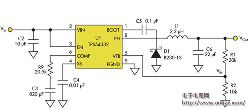
As long as a simple circuit is added to this diagram, the output voltage can be controlled by Vc. 
Vout - Vr = (Vfb - Vr) (R1+R2)/R2
R1 = 20 kΩ and R2 = 10 kΩ
VOut – Vr = 3 (Vfb – Vr)
VOut = 3 Vfb – 2 Vr(4)
Vr = 2 VRef – VC
VOut = 3 Vfb – 4 VRef + 2 VC
3 Vfb = 4 VRe
VOut = 2 VC
U1=0.8V, choose R7=10 kohm, R8=3.16 kohm
Vref=0.6V
Thus C1 reduces the output of U2 and ensures the stability of the U1 feedback loop.
Silicon Controlled Rectifier (SCR)
Silicon Controlled Rectifier (SCR) is short for silicon controlled rectifier. SCRs are available in one-way, two-way, turn-off, and light control types. It has the advantages of small size, light weight, high efficiency, long life, easy control, etc. It is widely used in occasions such as controllable rectification, voltage regulation, inverter, and non-contact switches and other automatic control and high-power electric energy conversion.
Silicon Controlled Rectifier,Scr Silicon Controlled Rectifier,3 Phase Silicon Controlled Rectifier,Semiconductor Silicon Controlled Rectifier
YANGZHOU POSITIONING TECH CO., LTD. , https://www.yzpst.com