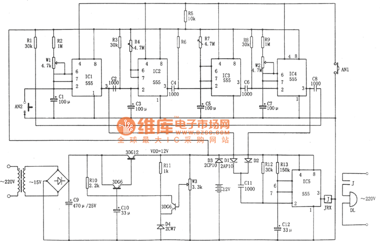
As shown in the figure, the classroom bell automatic control circuit. The controller comprises a step-down rectifier circuit, a loop program timing circuit, an execution control circuit and the like. IC1 to IC4. In order to trigger the delay circuit, the delay time can be realized by adjusting the charge and discharge time constant RC as needed. For example, the delay time of IC1 is td1=1.1(R2+Rw1)C1, and the remaining delay times are similar. IC5 is the ringing time timing control circuit, and the delay time is td5=1.1R13C12, and the parameters shown in the figure correspond to about 10 seconds. The outputs of IC1 and IC4 in the loop program timer are respectively added to D1 and D2, and then through capacitor C11, and then the IC5 outputs a high level (3 pins). This level causes the relay to pull in, thereby turning on the power of the bell DL. . 
Through this circuit, the following time program of ringing can be realized: ringing -10 minute interval (class break) - ringing - 45 minutes class time - ringing - 1O minute interval ... thereby realizing automatic control of the ringing.
|
Type
|
Input Current
|
|
BR-AI
|
AC200-1000A
|
|
AC1200-2000A
|
|
|
AC2500-6300A
|
|
|
AC8000-20000A
|

Power Transducer,Electricity Transducer,Three Phase Current Transducer,Single Phase Current Transducer
Jiangsu Acrel Electrical Manufacturing Co., LTD. , https://www.acrel.com.pk