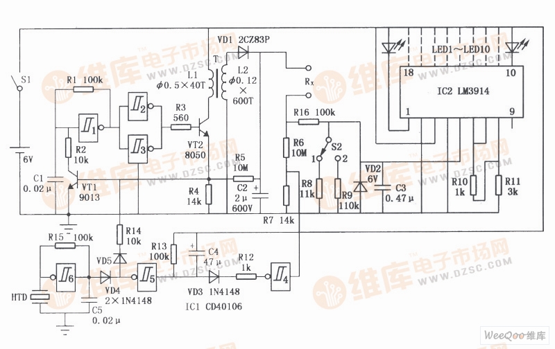
Portable megohmmeter circuit
The portable megohmmeter circuit is shown in the figure. ICl is a six Schmitt trigger CD40106, in which the flip-flop l constitutes an oscillating circuit, and the flip flops 2, 3 constitute a driving circuit. The oscillating signal output by them drives the switching tube VT2 to work, and then the transformer T is boosted and the diode VD1 is rectified to obtain a 500V DC test voltage. The voltage division of the resistors R4 and R5 controls the on-resistance of the tube VT1 to change the pulse width of the oscillation signal so that the 500V DC voltage remains stable during measurement. IC2 is a recorder-specific display integrated circuit LM3914, and its output terminal is connected with LEDs LED1l10l to display the size of the measured resistance Rx. IC5's 5-pin input voltage is incremented by 0.5V, so that the ten output terminals of IC2 output low level from 10 feet to 1 foot, so that the corresponding LED emits light, indicating the resistance of the measured resistance. When the changeover switch S2 is set to "1", the measurement range is 1 to 10 MΩ; when S2 is set to "2", the measurement range is 10 to 100 MΩ. The flip-flops 4, 5, and 6 in the ICl constitute an insulation resistance test circuit. When the insulation resistance is short-circuited, the flip-flop 4 outputs a high level. After a delay of 5 seconds, the flip-flop 5 also outputs a high level, so that VTl is saturated and turned on, and the oscillation circuit composed of the flip-flop l stops, and the flip-flop 6 is composed. The oscillating circuit causes the piezoelectric ceramic sheet HTD to emit an audible sound. When the short-circuited insulation resistance is removed, the circuit automatically returns to the normal state after 5 seconds. The Zener diode VD2 protects the IC2 during the insulation resistance test.
Reloj Inteligente
Reloj Inteligente
everyone enjoys luck , https://www.eeluck.com