First, the installation of rack PDU
1.1. According to the vertical installation of two products in each cabinet, the product is fixedly installed in the appropriate position on both sides of the cabinet, as shown in Figure 1 below:
1.2. Select any one of the products as the host, and the other as an auxiliary machine, the main and auxiliary machines need to be set (refer to the product manual);
1.3. A host can cascade 4 sub-machines through a straight-through network cable, and 5 devices are a group, occupying one IP address.
Second, the network diagram
2.1. Select IP-PDU1 in the cabinet 1 as the host, and set the IP-PDU2~IP-PDU5 as the slaves from Slave1 to Slave4 respectively (Note: For the setting method, refer to the “Device setting†chapter in the instruction manual.)
2.2, through the straight-through cable to cascade it, refer to Figure 3;
2.3 Connect the IP-PDU1 NET port through a common network cable and connect it to the LAN. The IP-PDU1 IP address is used to implement remote monitoring of the group of IP-PDU products. The networking of this group of products is completed, as shown in Figure 4;
2.4. According to this method, complete the networking configuration of other products.
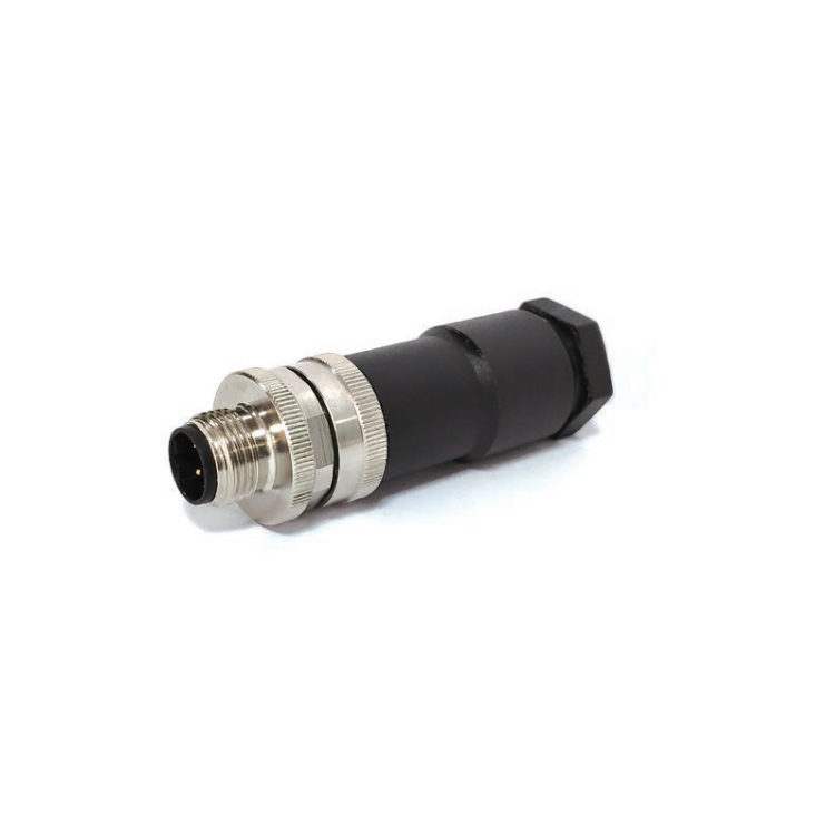
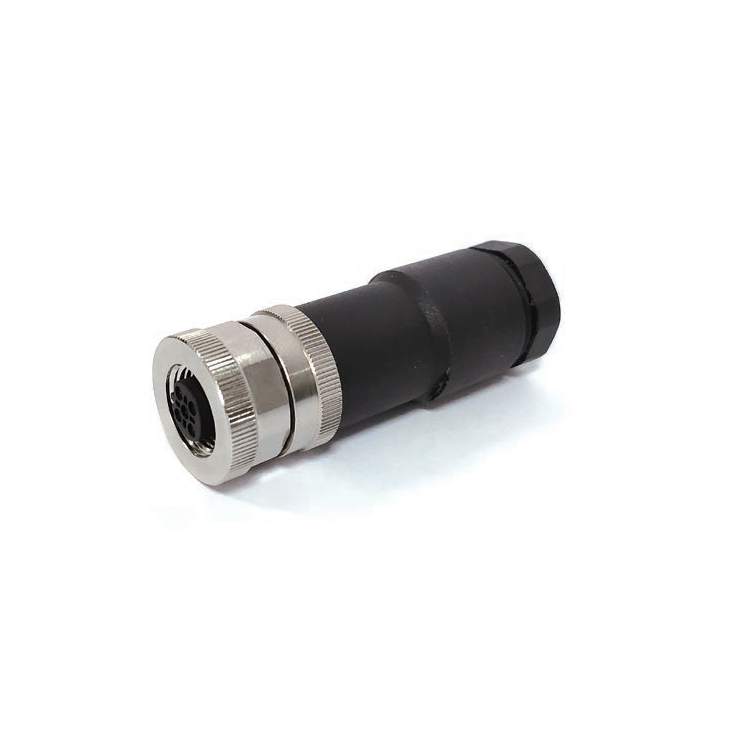
M12 Connection Cable provides a wide range of metric for small Sensors and actuators. The connector system provides a future-proof interface that supports higher-bandwidth needs, meeting the requirements of up to 10GB/s. Connectors are either factory TPU over-molded or panel receptacles supplied with sold-cup for wire connecting or with PCB panel solder contacts. Field attachable / mountable Connector is also available for your choice.


M12 Connector,M12 power connector,Right Angle Connector,M12 panel mount Connector, M12 shielded connector
Kunshan SVL Electric Co.,Ltd , https://www.svlelectric.com