With the existing tape recorder in the home, you can record when both parties talk, and automatically answer and record the other party's message when no one is at home.
As shown in the figure on the right, the circuit consists of ringing current detection, audio detection, R-S trigger, response voice module and analog electronic switch. When the owner goes out, set S1 to "1" and the circuit is in the automatic message state. If the local telephone is called, the ringing signal (90V, 25Hz) sent by the telephone lines X1 and X2 is rectified by VD1~VD4 through the DC blocking capacitor C1 and the current limiting resistor R1, and the output DC voltage is applied to the optical coupler ( 4N25) 1, 2 feet, so that the photocell between 4 and 5 feet is turned on. Then the output level of the 4-pin is changed from 0 to 1, and is added to the IC3 (TP-1106K) 1 pin to trigger its operation.
IC1 uses a three-two-choice analog electronic switch CD4053. The R-S flip-flop IC4 is composed of a NOR gate CD4001. R3 and C2 are automatic reset circuits. When the power is turned on, the voltage at both ends of C2 cannot be abruptly changed. The S terminal is controlled by IC56 to be 1, so RS=11, the output terminal Q=0; then C2 is charged and R is lowered. It is low, that is, RS=01, and the state of Q=0 will be maintained. S2 is the set switch. The audio detection circuit IC5 uses NJM2072, which contains audio amplification, detection, analog electronic switch, Schmitt trigger, buffer amplifier and constant current source, etc., 6 and 7 feet are complementary output terminals, when 1 pin has no audio signal input, 6 feet are 1, 7 feet are 0; when there is a signal, 6 feet become 0, 7 feet become 1. After canceling the audio signal, the output maintenance time of pins 6 and 7 is determined by C7, and can generally be estimated by T=0.2C7. The RP is used to adjust the amplification gain and change the detection sensitivity. In summary, after the power is turned on, the relevant control terminals are initialized to: 6 pins of IC5 are 1, 7 pins are 0; Q of the R-S flip-flop is 0; and control terminals A1 to A3 of three electronic switches in IC1 are respectively 0, that is, {12}, {14} feet are turned on, 4, 5 feet are turned on, {15}, 2 feet are turned on.
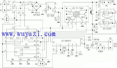
As mentioned above, if the IC31 pin is triggered by a high level when there is a ringing signal, the audio signal output by the 5 pin is added to the IC51 pin via IC1{12}, {14}, and C5. At this time, the IC56 pin changes, the input of the R-S flip-flop RS=00, the output state of Q=0 is still maintained; and the IC57 pin becomes 1, on the one hand, the pin 9 and 10 of the electronic switch are applied to make it 1, {15}The foot and the 3rd and 4th feet are respectively turned on. The voice message of "Hello! The master is not present, please leave a short message" from the IC35 foot is passed through IC1{12}, {14}, 1, {15} foot and C3. S1 is transmitted to the other party, waiting for the message; on the other hand, the LED is positively illuminating, the bidirectional thyristor BCR is turned on, the recorder is powered on, the motor starts to rotate (the tape is pre-installed, and the recording button and the power switch are pressed). However, at this time, the IC3{13} and {14} pins are disconnected, so the tape is only idling, and the response signal output from the IC35 pin is not recorded on the tape. P3 is connected to the MIC jack of the recorder, P4 is the power jack of the recorder, and P5 is connected to the AC mains.
When the response signal output from the IC35 pin ends, its 3 pin outputs a positive pulse and is applied to the S terminal of the flip-flop to flip it, that is, the Q output changes from 0 to 1. At this time, the electronic switch IC1 has a footstep of 1, the {14}, and {13} feet are turned on, and the other party's message passes through the conduction pins {15}, 1, {14}, and {13 of C3, C4, and IC1. } and 4, 3 feet are sent to the recorder via P3 and recorded on the tape. During the answer and message, the IC51 pin always has an audio signal input. When the message ends, the IC51 pin loses the audio signal, the 7-pin output changes to 0, the IC19 and 10 pins also go to 0, and the IC1's {15}, 1 pin and 4 and 3 pins are disconnected. At the same time, IC6's 6 pin changes to 1, triggering the R-S flip-flop to make Q=0, IC1{11} pin is 0, {14}, {12} foot is turned back on, the circuit returns to the initial waiting state, waiting Next message. Since C1 is small and R1 is large, the other message signal does not make the optocoupler work.
When S1 is set to "2" position, the telephone TEL is turned on, and the telephone can be normally ringed and dialed. At this time, IC2 and IC3 have no effect. The IC51 pin has an audio signal during the call, so its 6-pin output is 0, the R-S flip-flop Q=0 (see above), the IC1{14}, {12} pins are in the on state; and the IC5 7-pin is changed to 1 , IC1's {15}, 1 foot and 4, 3 feet are connected (these feet are useless at this time). At this time, if you want to record the phone, press the recorder's power switch to turn on the BCR (because IC57 is already 1), press the record button, then press S2 to trigger the R-S trigger to make Q=0. Then, the {14} and {13} pins of IC1 are connected, and the telephone recording starts. After the recording is completed, the IC57 pin becomes 0, and the recorder stops.
Fiberglass Rod,ECR Rod,Corrosion Core Rod Materials for Insulators
TAIZHOU HUADONG INSULATED MATERIAL CO.,LTD , https://www.thim-insulator.com