∠This article will discuss the challenges that signal integration and hardware engineers face when designing or debugging connections up to several Gb per second. Whether it's next-generation high-resolution video display, medical imaging, data storage or in the latest high-speed Ethernet and telecom protocols, we all face the same signal integration challenges. Then start the discussion from excessive equilibrium. âˆ
Serializers and Deserializers (SERDES) and Field Programmable Gate Arrays (FPGAs) in modern application specific integrated circuits (ASICs) typically achieve excellent cross-channel connectivity with up to 30 dB loss. Longer or more lossy channels often require the help of a signal conditioner such as a retimer or repeater. These devices compensate for the effects of long channels and provide the system with the necessary ability to drive additional distances.
One of the main functions of a repeater or retimer is to compensate for the insertion loss of the channel. This function can be broken down into receive equalization and transmit equalization. The receive equalization circuit is typically composed of a continuous time linear equalizer (CTLE) and occasionally a decision feedback equalizer (DFE). De-emphasis or finite impulse response filters (FIR) are common options for transmit equalization circuits. The receive equalization circuit amplifies the signal for the long channel to compensate for frequency dependent losses. The transmit equalization circuit adjusts the shape of the transmitted signal so that the signal is more easily recovered after the channel is weakened.
For receive equalization and transmit equalization, it is important to apply an appropriate amount of equalization. The applied balance is too small (underbalanced) that the signal cannot be fully recovered. However, applying too much equalization (over-equalization) can also be problematic because over-equalized waveforms can interfere with the receiver's ability to recover data.

Figure 1 shows two examples of eye diagrams. One eye diagram makes the appropriate adjustments to the channel (left), while the other eye diagram shows the signal that is overbalanced (right).

Figure 1: Adjusting the appropriate eye diagram and over-balanced eye diagram
The two eye diagrams have the largest difference at the 0V intersection. The over-equalized eye diagram on the right shows separation between the rising and falling edges. This phenomenon is often referred to as "double strips." Double strips can interfere with the receiver's ability to detect frequencies properly or maintain a correct phase relationship with the input data.
Using the oscilloscope's jitter decomposition feature, you can see in Figure 2 how the overbalanced eye diagram shows the bimodal jitter content. In other words, the jitter is distributed over two frequencies, the average being the data rate, not the actual data rate itself. Further tests have shown that this bimodal jitter distribution is related to data-dependent jitter and is directly affected by the equalization applied by the equalizer.
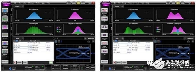
Figure 2: Adjusting the jitter decomposition of appropriate and excessively balanced eye diagrams
There are many ways to overbalance; Figure 3 is a more classic example. On the left is an appropriately balanced eye diagram. The over-equalized eye diagram on the right side shows that the amplitude of the double-striped eye and the bit transition are too large. In this case, too large a bit transition can cause a match between logic high and logic low compatibility with system specifications. Also pay attention to the difference between the jitter profiles.
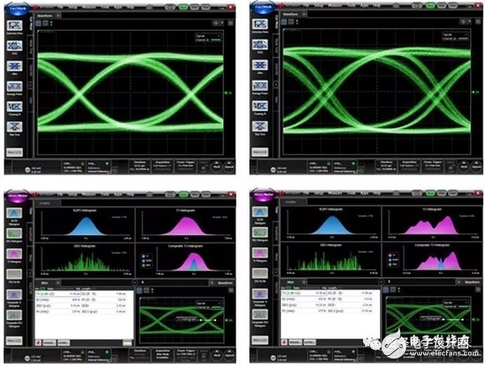
Figure 3: Another embodiment of over-equalization - overshooting double strips
Keep eye diagrams horizontally and vertically when adjusting and optimizing connections for optimal performance. It's easy to maximize one of them, but be sure to avoid over-equalizing the signal, otherwise it will increase the bit error rate.
2 In 1 Laptop
Do you know the difference of Yoga Laptop and 2 in 1 laptop? No. 1 is yoga notebook with 360 flip rotating absolutely; No.2 is laptop yoga slim is just like normal Education Laptop-connecting screen with keyboard, but 2 in 1 laptop tablet with pen is separately, you can use the monitor part as a window tablet. In one word, every intel yoga laptop have all the features and function of tablet 2 in 1 laptop except separated screen and keyboard. From the cost, windows yoga laptop is much higher than 2 in 1 type., cause usually former with more complicated craft and quality.
What other products you mainly produce? It`s education laptop, Gaming Laptop, engineering laptop, Android Tablet, mini pc and All In One PC. You can see more than 5 different designs on each series, believe always have right one meet your special application or your clients demands. Therefore, what you need to do is just to get all the requirement details from your clients, then share the complete information with us, then we can provide the most suitable situation.
Of course, you can also call or email or send inquiry of what you need, thus can get value information much quickly.
2 In 1 Laptop,2 In 1 Laptop Sale,2 In 1 Laptop Tablet With Pen,Tablet 2 In 1 Laptop,2 In 1 Laptop Deals
Henan Shuyi Electronics Co., Ltd. , https://www.shuyielectronics.com