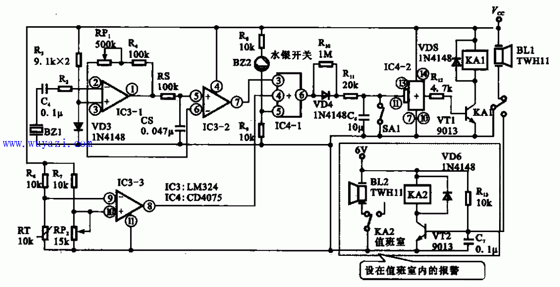
The figure above shows a safe anti-theft alarm circuit. The circuit is mainly composed of voltage electric sensor BZ1, tilt sensor B22, temperature sensor RT, voltage comparator IC3 and other components.
The piezoelectric sensor BZ1 is connected to the input terminal of the voltage comparator IC3-1. When it is subjected to vibration, an electrical signal is generated. The electrical signal is amplified by IC3-1 and IC3-2 and then passed through the OR gate IC4-1 and IC4-. 2 to drive the transistor VT1. Turning on VT1 will cause the relay to operate, and the contact of the relay will turn on the alarm buzzer.
There is also a tilt sensor (mercury switch) on the safety lock. When someone moves the safe, the mercury switch on the safety lock is turned on, or the @pin of the gate circuit IC4-1 also outputs a high level to alarm.
The third sensor is a temperature sensor. When the safe is subjected to high heat, the resistance value of the thermistor RT decreases, and the 8-pin output of IC3-3 is applied to the OR circuit IC4-1 to make the alarm circuit operate.
Asic Power Supply,High Power Uninterruptible Power Supply,Active Computer Power Supply,4000W Computer Power Supply
Boluo Xurong Electronics Co., Ltd. , https://www.greenleaf-pc.com