Controller Area Network CAN is a serial, multi-master communication specification for connecting electronic control modules, sensors and actuators in automotive and industrial applications. Because CAN bus has strong error correction capability, supports differential transmission and transmission, and long transmission distance, CAN bus is widely used. It has become the mainstream technology and basic technology in the field of industrial data communication. At present, TTCan, DeviceNet, is more popular. CANo-pen, SAE J1939 and other specifications are based on CAN, so in-depth study of CAN bus is very necessary. In the CAN specification, bit timing and synchronization mechanism is one of the important and difficult to understand. It is not only related to the understanding of baud rate, bus length and other related content, but also has a direct impact on the success of node development. . However, the current literature lacks detailed analysis and discussion of CAN bus timing and synchronization mechanisms. Based on the CAN technical specification, this paper deeply analyzes the bit timing and synchronization mechanism of the CAN bus, gives the definition of hard synchronization and resynchronization, and gives the corresponding graphical interpretation mode. The composition and structure of the alignment time and the synchronization occur. The key content of how time and synchronization are carried out gives a clear and specific analysis. The work here has a high reference value for understanding the nature of the bit timing and synchronization mechanism and setting the parameter time parameters.
1 bit timing1.1 bit time composition
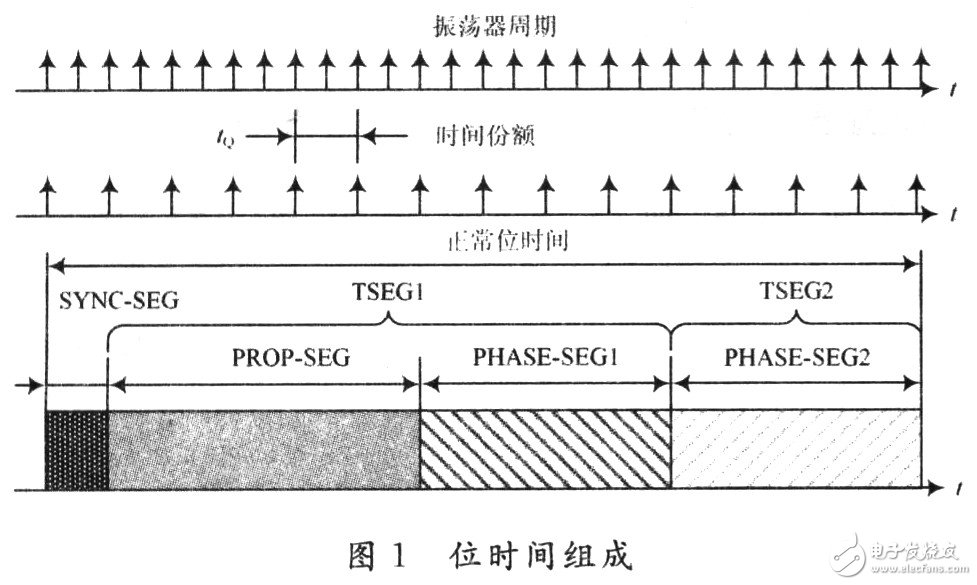
The bit time (bit period) tB is the duration of 1 bit. The normal bit time tNBT is the reciprocal of the normal bit rate fNBT (in the case of non-resync, with the number of bits transmitted per second by the ideal transmitter), ie tNBT=1/fNBT. The normal bit time can be divided into several non-overlapping time segments including: sync segment (SYNC-SEG), propagation time segment (PROP-SEG), phase buffer segment 1 (PHASE-SEG1), phase buffer Segment 2 (PHASE-SEG2). Each time period consists of an integer number of basic time units called time shares tQ. tQ is a fixed time unit derived from the oscillator period tCLK. The duration of a time share is usually a system clock cycle tSCL of CAN. tSCL can be adjusted with a programmable pre-scale factor. Each bit time must consist of 8 to 25 time shares. The composition of the bit time is shown in Figure 1.
Each time period of the bit time has its specific purpose:
(1) The synchronization segment is used to synchronize the nodes on the bus, and one hop edge is required to be located in the segment, and the segment length is one time share;
(2) The propagation time period is used to compensate the physical delay in the network, which is twice the sum of the signal propagation time on the bus, the input comparator delay and the output driver delay. The length of the segment is 1 to 8 times. Share
(3) The phase buffer section 1 and the phase buffer section 2 are used to compensate the phase error of the edge, and by resynchronization, the phase buffer section 1 can be extended or the phase buffer section 2 can be shortened.
The length of these time periods is programmable. In the commonly used communication controller (SJA1000) or PAC82C200, the combined propagation time period and phase buffer segment 1 are referred to as time segment 1 (TSEG1), and the phase buffer segment 2 is referred to as time segment 2 (TSEG2), as shown in FIG. Shown.
The sampling point is a moment at which the bus level is read and understood as its own value. It is located at the end of phase buffer segment 1. During resynchronization, the position of the sample point is shifted by an integer number of time shares, the maximum allowed value of which is called the resynchronization jump width (SJW), which can be programmed to 1 to 4 time shares. It is worth noting that the resynchronization jump width is not part of the bit time.
1.2 bit timing
The bit timing is done by the node itself (programmable), and the node performs bit timing as:
(1) determining the bit time to determine the baud rate (bit rate) to determine the network speed of the bus; or determining the bit time given the network speed of the bus;
(2) determining the length of each of the 1-bit components - the sync segment, the propagation period, the phase buffer segment 1 and the phase buffer segment 2, wherein the sync segment is used for hard synchronization and is located at the end of the phase buffer segment 1 The sampling point is used to ensure that the bus level is read correctly;
(3) Determine the resynchronization jump width for resynchronization.
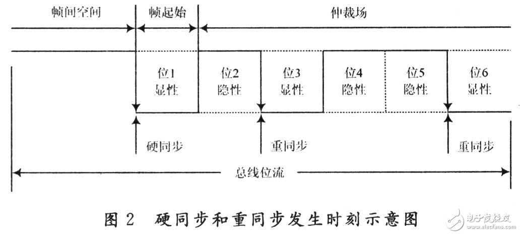
2 CAN bus synchronization mechanism analysisThe CAN specification defines its own unique synchronization method: hard synchronization and resynchronization. Synchronization is closely related to bit timing. Synchronization is done by the node itself, which will detect that the edge from the bus is compared to its own bit timing and that the bit timing is adapted (adjusted) by hard synchronization or resynchronization. In general, the edge from the bus that causes hard synchronization and resynchronization occurs is shown in Figure 2.
2.1 Hard synchronization
The CAN specification gives the results of hard synchronization and resynchronization, but does not give a definition of hard synchronization and resynchronization. Here we first give the definition of hard synchronization and resynchronization, and then analyze it.
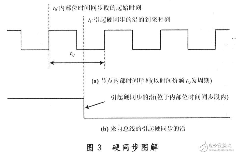
The so-called hard synchronization is detected by the node, and the edge from the bus immediately determines the starting position of the internal bit time (the starting time of the synchronization segment). The result of the hard synchronization is that the previous time (measured by the time share tQ) along the arrival time becomes the start time of the node internal time synchronization segment and the internal bit time is restarted from the synchronization segment. This is what the specification says "hard-synchronous forcing causes the hard-synchronized edge to be within the re-started bit-time sync segment." Hard synchronization is generally used for the beginning of a frame, ie the start position (synchronization segment) of the internal bit time of each node on the bus is determined by the leading edge of the frame start of a message frame from the bus.
The length of the sync segment is 1 time share. As shown in Figure 3. The edge from the bus causing hard synchronization arrives at time t1, and the node detects the edge. The previous time t0 (in tQ period) at time t1 is taken as the start time of the internal bit time synchronization segment.
2.2 Resynchronization
The so-called resynchronization means that the node adjusts its internal bit time according to the size of the phase error so that the internal bit time of the node is close to or equal to the bit time of the message bit stream from the bus. As a result of the resynchronization, PHASE-SEG1 can be extended or PHASE-SEG2 can be shortened so that the node can correctly receive the message. Resynchronization is typically used during bitstream transmission of frames to compensate for inconsistencies in the oscillator frequencies of the various nodes. This involves the concept of phase error along. The phase error is given by the position along the time synchronization segment relative to the internal bit of the node, measured by time share, and the sign along the phase error is e, which is defined as follows:
(1) If the edge is within SYNC~SEG, then e=0;
(2) If the edge is before the sampling point (within TSEG1), then e "0;
(3) If the edge is after the sampling point of the previous bit (within TSEG2), then e "0".
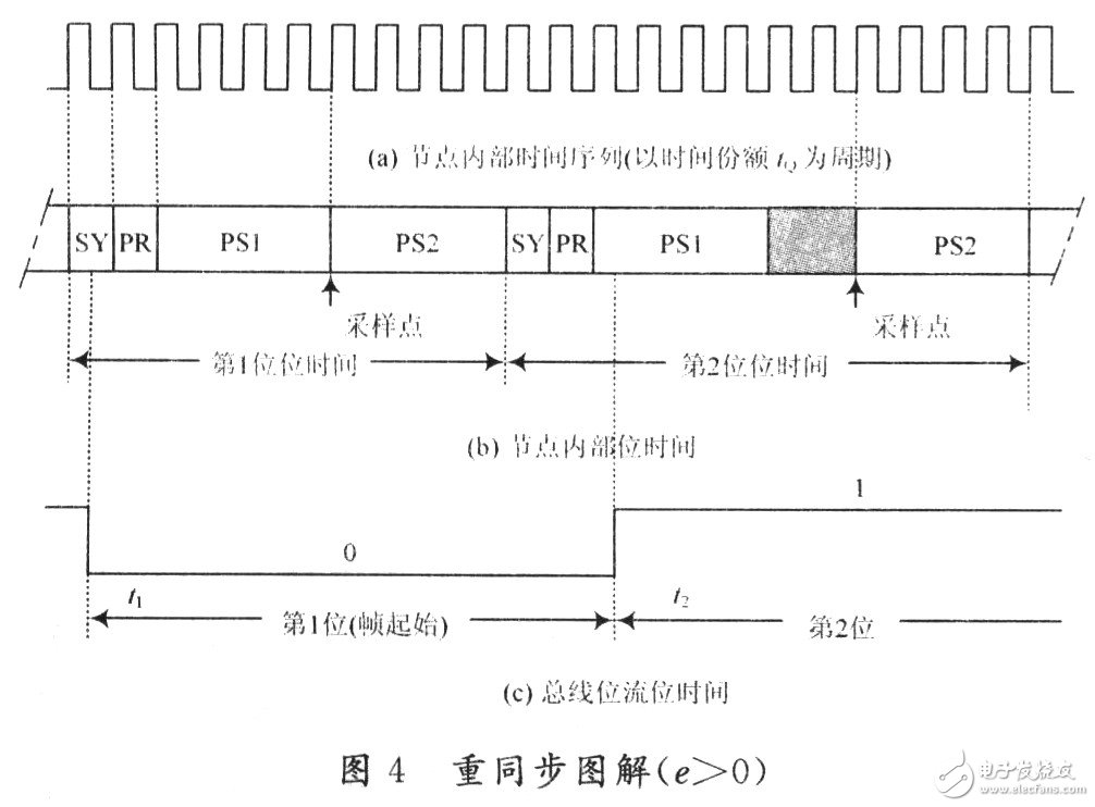
The resynchronization jump width, resynchronization strategy and synchronization rules are also given in the CAN specification, but they are more abstract and difficult to understand. To gain a deep understanding of how nodes are resynchronized, Figure 4 shows an illustration of resynchronization. In FIG. 4, SY, PR, PS1, and PS2 represent a sync segment, a propagation segment, a phase buffer segment 1, and a phase buffer segment 2, respectively. Assume that the first bit of the bus bit stream (start of frame, "0") starts at time t1 and ends at time t2, the second bit of the bus bit stream is "1"; starting from the second bit, the bus bit stream The “recessive†(“1â€) to “dominant†(“0â€) and “dominant†(“0â€) to “recessive†(“1â€) transition edges are used for resynchronization. At time t1, the node detects the transition edge of the bus, and performs hard synchronization, so that the transition edge at time t1 is in the synchronization segment of the first bit time inside the node. The node starts the internal bit timing from the sync segment of the first bit, that is, the internal bit time is given according to the baud rate required by the system. It is assumed that due to the inconsistency of the oscillator frequencies of the respective nodes, the transition edge at time t2 is not within the synchronization segment SY of the second bit time of the node, but is within PS1, that is, there is e "0". This indicates that the bit time inside the node is less than the bit time of the bus bit stream. In order for the node to get the correct bit value from the bus, it is necessary to extend the bit time inside the node so that the internal bit time of the node is close to or equal to the bus bit stream time. Therefore, in this case, the resynchronization strategy that the node should adopt is to make PS1 extend a certain width (PS1 is extended by 2 time shares in FIG. 4, that is, the synchronization jump width is greater than or equal to 2 time shares, for example, 3 times. Share). The case of e "0 is similar, except that PS2 will shorten the width accordingly. This is consistent with the resynchronization strategy in the CAN specification.
3.1 Home Theater Speaker,Home Cinema System,Bluetooth Home Theatre,Home Theatre
GUANGZHOU SOWANGNY ELECTRONIC CO.,LTD , https://www.jerry-power.com