At present, with the widespread use of common small household appliances such as Walkman, pocket radio, camera, flashlight, electric shaver, and some portable instruments in the field of industrial measurement and control, high capacity, small internal resistance, high current discharge, The pot nickel battery, which has a long life and can be recharged, is reused, and the charger naturally becomes a must-have for every home and industrial site. This paper presents a circuit for charging an intrinsically safe power supply for a digital cable fault finder.
The power supply uses a set of 10GNYG4 cadmium nickel sealed alkaline battery pack, 4Ah12V, which requires standard charging, 0.4A charge for about 14 hours. This requires designing a constant current charging power supply with an output current of 0.4A. In the design, the TL431 precision adjustable power supply is used as the core component to form a charging circuit.
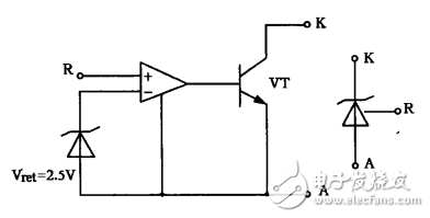
Figure 1TL431 equivalent circuit and circuit symbol
The equivalent circuit and circuit symbol of TL431 is shown in Figure 1. When the R terminal voltage is less than Vret=2.5V, the op amp output is negative, VT is not conducting, there is no current between K and A; when the R terminal voltage is greater than Vret=2.5V, the op amp output is positive, VT is on, K There is a current flowing between A and A. Therefore, the voltage between R and A can be stabilized at 2.5V, and since it is an integrated device, the voltage stability is relatively high.
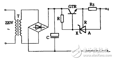
Figure 2 charging circuit
Using the above characteristics of the TL431, the circuit shown in FIG. 2 is constructed. The working principle is as follows: the power frequency alternating current is applied to the subsequent circuit after being stepped down, rectified, and filtered. GTR is used as the adjustment tube, and the voltage Vs across the resistor Rs should be about 2.5V. When Vs>2.5v, there is a current between K and A of TL431, bypassing the base current of GTR, causing the GTR set one emitter current to drop, and Vs returning to about 2.5V. This circuit uses Vs=2.5V, and sets the output current of this circuit to about 0.4A by setting a specific resistor Rs. It can be calculated that the rated power of the resistor Rs should be greater than 1W, so the winding resistance should be selected. In this circuit, the GTR operates in the linear region, and the power consumption is large, and a heat sink is required. In this way, the efficiency of the circuit is not very high, but it is an optional circuit for simple and less demanding applications.
Since 10 batteries are charged, the terminal voltage can reach 14v when the battery pack is fully charged. Considering the fluctuation of the power supply voltage and the tube voltage drop of the GTR, the secondary rated voltage of the step-down transformer is selected as 18V. This circuit has been proved by long-term application: the constant current characteristics are good, and it can meet the requirements of battery charging.
Stator and rotor laminations are an important part of motors and generators. The stator and rotor laminations are made of electrical steel by cutting and stamping. Usually the laminations are circular, and for those large motors or generators, the laminations are fan-shaped. Usually the thickness of the stator and rotor laminations is 0.2mm, 0.35mm, 0.5mm, 0.65mm, but depending on the application, there are thinner or thicker laminations. We are able to produce motors of various sizes from 100mm to 1250mm outer diameter. For larger motors or generators, we can also produce stator segment laminations.
Customizable Stator laminations,Customizable Rotor laminations,Segmented Stator laminations,Premanent Magent Rotor Lamination
Henan Yongrong Power Technology Co., Ltd , https://www.hnyongrongglobal.com