1, the resistance
Resistance equivalent circuit
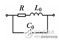
Figure 1 resistance equivalent circuit
Equivalent impedance of the resistor
The resistance values ​​measured by the same resistive element when passing through DC and AC are different. In the high-frequency AC, the influence of the lead inductance L0 and the distributed capacitance C0 of the resistive element must be considered. The equivalent circuit is shown in Fig. 1, where R is the ideal resistance. The figure shows that the equivalent impedance of this component at frequency f is
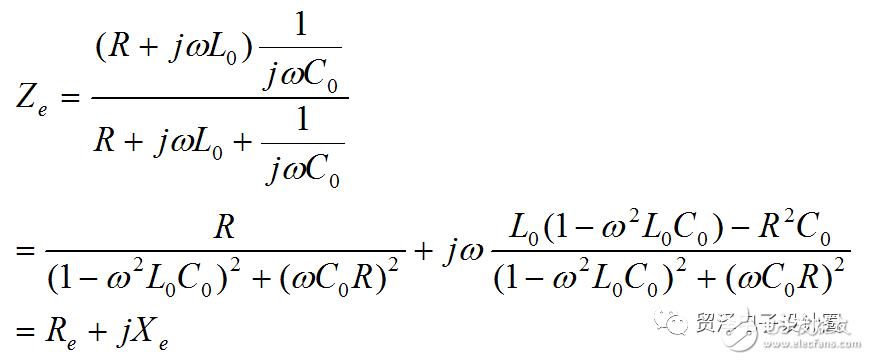
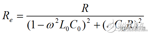
In the above formula, ω=2πf, Re and Xe are equivalent resistance components and reactance components, respectively, and
Equation 2
It can be seen from the above equation that Re is related to L0 and C0 in addition to f. This indicates that when L0 and C0 are not negligible, the resistance value of the resistance element is measured under AC, and the result will be Re instead of R value.
2, inductance
Inductance equivalent circuit
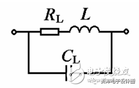
Figure 2 Inductance equivalent circuit
Equivalent impedance of the inductor
In addition to the inductance L, the inductive component always has a loss resistor RL and a distributed capacitor CL. In general, the effects of RL and CL are small. When the inductive component is connected to DC and reaches steady state, it can be regarded as a resistor. If it is connected to a low-frequency AC circuit, it can be regarded as a series connection of the ideal inductor L and the loss resistor RL. The equivalent circuit is shown in Figure 2 at high frequency. Comparing Fig. 1 and Fig. 2, it can be seen that the two are actually the same, and the high frequency equivalent impedance of the inductance component can be determined by referring to Equation 1.
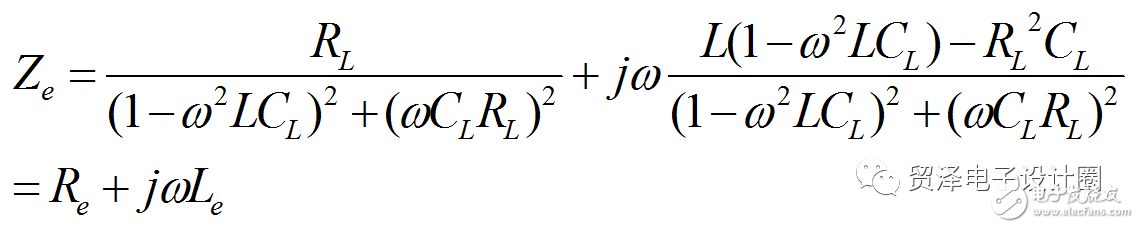
Equation 3
Where Re and Le are the equivalent resistance and equivalent inductance of the inductive component, respectively.
It is known from the above formula that when CL is too small or RL, CL and ω are not large, Le will be equal to L or close to equal to L.
3, the capacitor
Capacitance equivalent circuit
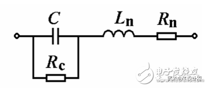
Figure 3 capacitor equivalent circuit
Equivalent impedance of capacitor
The capacitor component always has a certain dielectric loss under AC, and its lead also has a certain resistance Rn and a distributed inductance Ln. Therefore, the equivalent circuit of the capacitor component is as shown in FIG. In the figure, C is the inherent capacitance of the component, and Rc is the equivalent resistance of the dielectric loss. Equivalent impedance is
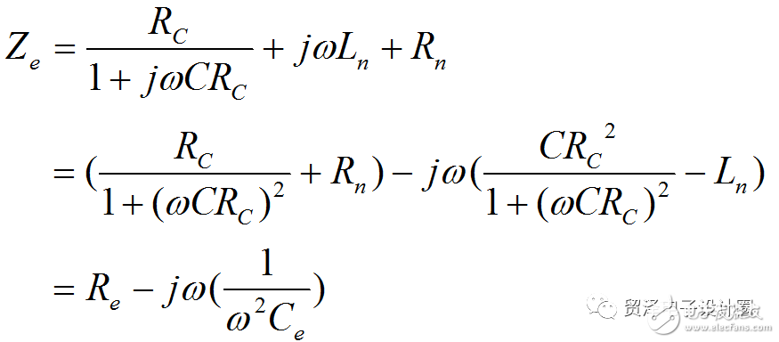
Equation 4
Where Re and Ce are the equivalent resistance and equivalent capacitance of the capacitive element, respectively, since the general dielectric loss is negligible (ie Rc → ∞), Ce can be expressed as
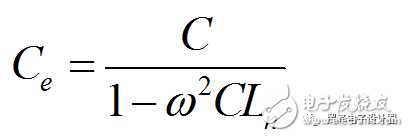
Equation 5
It can be seen from the above discussion that R, L, and C are measured under AC, and the actual measured values ​​are the equivalent values ​​Re, Le, and Ce; since the actual impedance of the resistor, capacitor, and inductor varies with the environment and the operating frequency. Therefore, in the impedance measurement, it should be carried out according to the actual working conditions (especially the working frequency). Otherwise, the measured result will have a large error or even a wrong result.
4, diode
Forward conduction equivalent circuit of power diode
(1): equivalent circuit
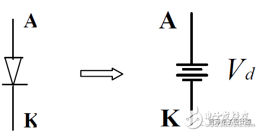
(2): Description:
When the diode is forward-conducting, a voltage drop equivalent can be used. The voltage is related to the temperature and the current flowing. When the temperature rises, the voltage becomes small; when the current increases, the voltage increases. Detailed relationship curves are available from the manufacturer's manual.
Reverse cut-off equivalent circuit of power diode
(1): equivalent circuit
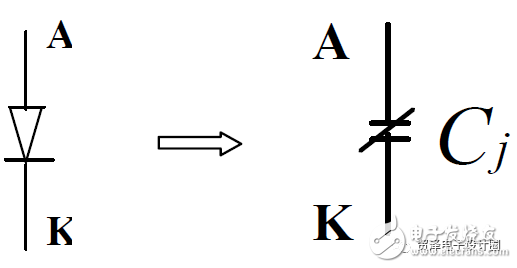
(2): Description:
When the diode is reverse-cut, a capacitor equivalent can be used. Its capacity is related to the applied reverse voltage, ambient temperature, etc., and the size can be obtained from the manufacturer's manual.
Summary of steady state characteristics of power diodes
(1): Current/voltage curve of the power diode at steady state
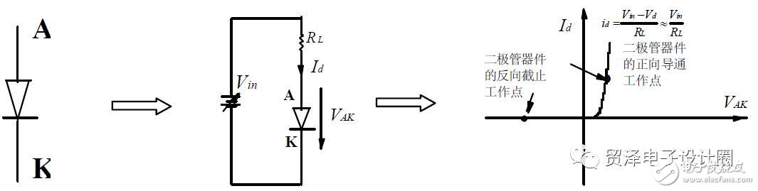
(2): Description:
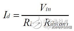
Steady-state operating point when the diode is forward-conducting:
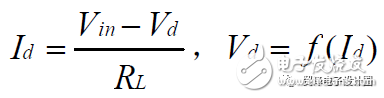
When Vin >>Vd, there are:
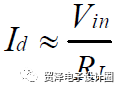
Vd ranges from 0.35V to 2V for different diodes.
Steady-state operating point when the diode is reverse-cut: Id≈0, Vd = -Vin
(3): Summary of steady state characteristics:
-- is a one-way conductive device (no forward blocking capability);
-- for uncontrollable devices, controlled by the polarity of their two-off voltage, no other external control;
-- Ordinary diodes have a large power capacity, but the frequency is very low;
-- There are three types of switching diodes, which have different steady-state characteristics and switching characteristics:
-- fast recovery diodes;
-- Ultra fast recovery, soft recovery diodes;
-- Schottky diode (reverse blocking voltage drop < 200V, no reverse recovery problem);
-- The forward current rating of the device is nominal by its average value; as long as the actual current average does not exceed its rating, ensuring that there is no problem with heat dissipation, the device is safe;
-- The on-state voltage of the device has a negative temperature coefficient, so it cannot be used directly in parallel;
-- Current SiC power diode devices have excellent reverse recovery characteristics.
5, MOS tube
Forward conduction equivalent circuit of power MOSFET
(1): equivalent circuit
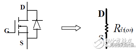
(2): Description:
When the power MOSFET is conducting in the forward direction, a resistor equivalent can be used. The resistor is temperature dependent, and the temperature is increased, and the resistor becomes large; it is also related to the magnitude of the gate driving voltage, and the driving voltage is increased, and the resistor becomes small. Detailed relationship curves are available from the manufacturer's manual.
Reverse conducting equivalent circuit of power MOSFET (1)
(1): Equivalent circuit (gate is not controlled)
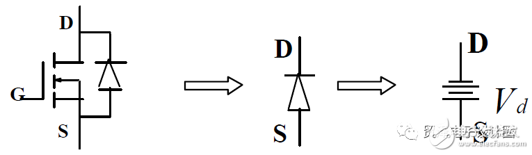
(2): Description:
That is, the equivalent circuit of the internal diode can be equivalent to a voltage drop. This diode is the body diode of the MOSFET. In most cases, it should be avoided because of its poor characteristics.
Reverse conducting equivalent circuit of power MOSFET (2)
(1): Equivalent circuit (gate plus control)
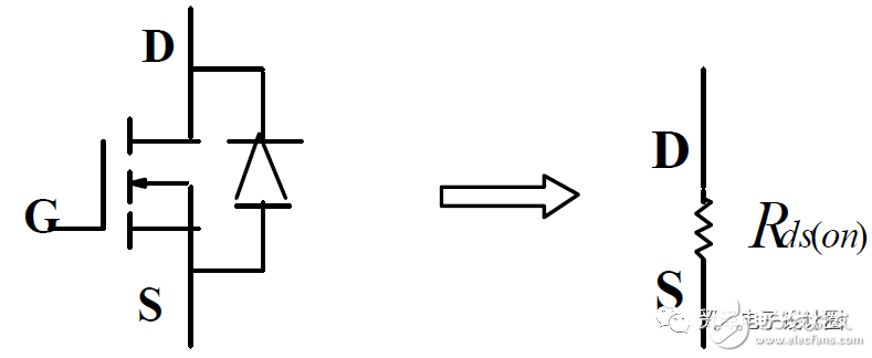
(2): Description:
The reverse directional conduction of the power MOSFET under the gate level control can also be equivalent to a resistor. The resistor is temperature dependent, and the temperature increases, the resistor becomes large; it is also related to the magnitude of the gate driving voltage, and the driving voltage is increased. This resistance becomes small. Detailed relationship curves are available from the manufacturer's manual. This working state is called synchronous rectification of the MOSFET and is a very important working state in the low-voltage high-current output switching power supply.
Forward cutoff equivalent circuit of power MOSFET
(1): equivalent circuit
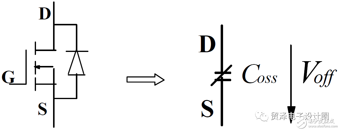
(2): Description:
The power MOSFET can be equivalent to a capacitor when it is turned off. Its capacity is related to the applied forward voltage, ambient temperature, etc., and the size can be obtained from the manufacturer's manual.
Summary of Steady-State Characteristics of Power MOSFETs
(1): Current/voltage curve of the power MOSFET at steady state
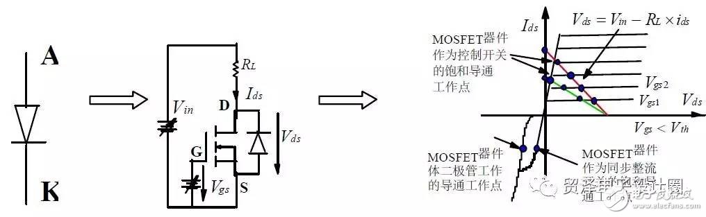
(2): Description:
Steady-state operating point when the power MOSFET is forward saturated:
When the gate is uncontrolled, its reverse-conducting steady-state operating point is the same as the diode.
(3): Summary of steady state characteristics:
-- the voltage Vgs between the gate and the source controls the conduction state of the device; when Vgs
-- The drain current rating of the device is nominal by its rms or average value; as long as the actual drain current rms does not exceed its rating, ensuring that there is no problem with heat dissipation, the device is safe;
-- The on-resistance of the device has a positive temperature coefficient, so it is easy to expand in parallel in principle, but in actual parallel, the symmetry of the drive and the dynamic current sharing problem should be considered.
-- The current Logic-Level power MOSFET, with a Vgs of 5V, ensures that the on-state resistance of the drain source is small;
-- The device's synchronous rectification operation has become more and more extensive because its on-state resistance is very small (currently the smallest is 2-4 milliohms), and it is the most DC/DC in low-voltage high-current output. Key device
Power MOSFET equivalent circuit including parasitic parameters
(1) equivalent circuit
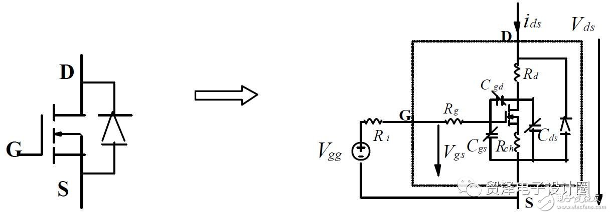
(2) Description:
The actual power MOSFET can be equivalent to three junction capacitors, three channel resistors, and an internal diode and an ideal MOSFET. The three junction capacitances are all related to the junction voltage, and the gate resistance of the gate is generally small. The sum of the two channel resistances of the drain and source is the on-resistance of the MOSFET when it is saturated.
Sky Curtain,Led Grille Screen,High Resolution Display Screen,Led Grille Screen
Kindwin Technology (H.K.) Limited , https://www.ktlleds.com