A feedback control system used to accurately follow or reproduce a process. In many cases, the servo system refers to a feedback control system in which the controlled amount (output of the system) is mechanical displacement or displacement velocity and acceleration, and its function is to make the mechanical displacement (or rotation angle) of the output accurately track the displacement of the input ( Or corner). There is no principle difference between the structural composition of the servo system and other forms of feedback control systems.
Advantages of the servo control system1. Accuracy: The closed-loop control of position, speed and torque is realized; the problem of stepping motor out-of-step is overcome; the accuracy of the size and bending angle of the finished product is ±1;
2, the speed: high-speed performance is good, the general rated speed can reach 2000 ~ 3000 rpm;
3. Adaptability: It has strong anti-overload capability and can withstand three times the rated torque. It is especially suitable for occasions with transient load fluctuations and quick start.
4. Stable: It runs smoothly at low speed, and does not produce stepping operation similar to stepper motor when running at low speed. Suitable for occasions with high speed response requirements;
5. Timeliness: The dynamics of motor acceleration and deceleration are short, generally within tens of milliseconds;
6, comfort: heat and noise are significantly reduced.
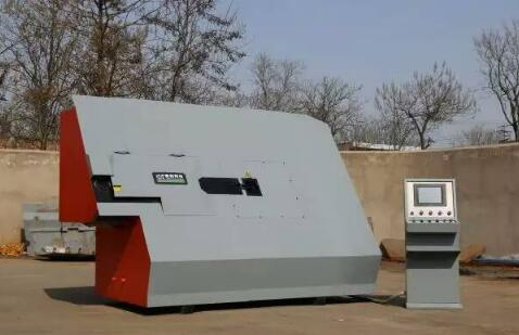
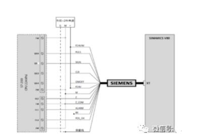
Take the SINAMICS V80 system as an example. The SINAMICS V80 servo drive system consists of a servo drive and a servo motor. The servo drive is always used with its corresponding servo motor of the same power. The SINAMICS V80 servo drive accepts the pulse sequence sent from the host controller through the pulse input interface, controls the speed and position, and completes the control of the drive operation and the output of the real-time status through the digital interface signal.
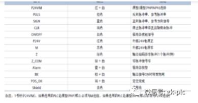
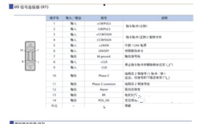
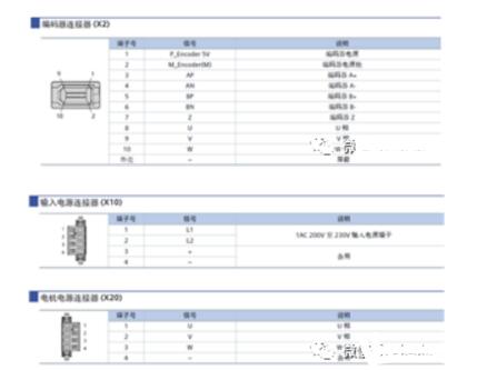
There is a pulse setting rotary switch on the drive to design the pulse resolution and command pulse type. This design choice 3, the corresponding resolution is 10000. The corresponding functions of the four connectors X1, X2, X10 and X20 of the drive are shown in Figure 3:
The hardware composition of the servo motor control system is shown in Figure 4. The S7-200 sends a high-speed pulse and motor rotation direction signal according to the requirements, and the servo motor is controlled to rotate by the driver; the output signal of the motor rotary encoder forms the A-phase and B-phase orthogonal signals through the driver, and is converted into the S7-200 high-speed signal after the signal conversion. The signal source of the counter forms a closed-loop control system with the S7-200 as the processor. Shielded cables are used between the servo motor, servo drive and S7-200PLC.
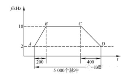
When designing the servo motor, considering the smooth start and stop of the servo motor, a three-stage pulse mode is designed. The schematic diagram is shown in 5. The pulse is divided into three segments, that is, rising, constant speed, and falling. The rising segment is the starting speed rising from a relatively low value to a relatively high value, and the falling segment is the motor braking speed from a relatively high value. The value of the value is reduced to a relatively small value, which is beneficial to protect the motor. Defining both the rising and falling segments is a hundred pulses, and the remaining pulses that need to go are run at high speed in the constant speed segment. In addition, when the number of pulses to be taken is less than two hundred, the single-segment low-speed is taken. In each pulse subroutine, it is first judged whether to go in single-segment or three-segment.
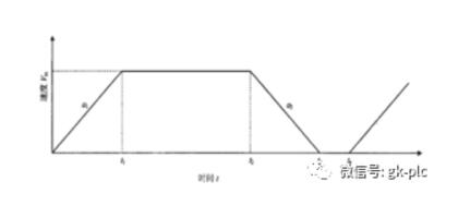
Figure 5 three-stage pulse diagram
In order to cooperate with the control of stepping and servo motor, Siemens PLC has built-in pulse output function and set corresponding control commands, which can control the stepping and servo motor well.
This section will focus on the Siemens S7-200 PLC pulse output function and stepper motor control. The servo motor control is basically the same as the stepper motor. Stepping and servo control can also be implemented in the S7-300/400 PLC through the FM module. The idea is the same as that of the S7-200 PLC. This section is not introduced.
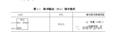
1, pulse output (PLS) instruction
The pulse output (PLS) instruction function is: When enabled, checks the special memory bit (SM) for the pulse output (Q0.0 or Q0.1) and then performs the pulse operation defined by the special memory bit. The format of the instructions is shown in Table 9-3.
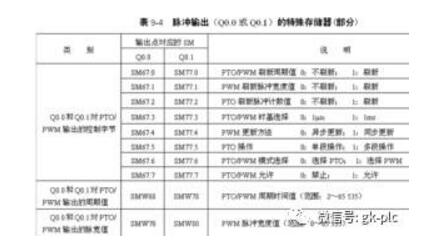
2. Special memory for pulse output (Q0.0 or Q0.1)
Each PTO/PWM generator has a control byte (8 bits), a pulse count value (unsigned 32-bit value), a time period, and a pulse width value (unsigned 16-bit value). These values ​​are placed in a specific Special Storage Area (SM), as shown in Table 9-4. When the PLS instruction is executed, the S7-200 reads these special memory bits (SM) and then performs the pulse operation defined by the special memory bits, ie the corresponding PTO/PWM generator is programmed.
3. Sharing of Q0.0 and Q0.1
The PTO/PWM generator and output image registers share Q0.0 and Q0.1. When the PTO or PWM function is used in Q0.0 or Q0.1, the PTO/PWM generator controls the output and disables the normal use of the output point. The output waveform is not affected by the output image register status, output forcing, and execution of the immediate output command. When the PTO or PWM function is not used at the Q0.0 or Q0.1 position, the output image register controls the output, so the output image register determines the initial and end states of the output waveform, that is, the pulse output waveform is determined to be high or low. And end, causing the output waveform to have a short discontinuity.
4, linear pulse train output (PTO)
The PTO can achieve the output of a high-speed pulse train with a duty cycle of 1:2. The number of pulses and period can be defined by the user. The most significant bit (idle bit) in the status byte is used to indicate if the burst output is complete. The interrupt program can be started when the burst is completed. If a multi-segment operation is used, the interrupt program is started when the envelope table is completed.
5, pulse width adjustable pulse (PWM) output
PWM is a high-speed pulse output with adjustable pulse width. By controlling the pulse width and pulse period, the control task is realized.
The stepping motor has an acceleration and deceleration process when starting and stopping, and the smaller the acceleration, the smaller the impact and the smoother the motion. Therefore, the stepping motor generally has to undergo such a change process: acceleration → constant speed (high speed) → deceleration → constant speed (low speed) → stop. The stepping motor speed is proportional to the pulse frequency, so the pulse frequency of the input stepping motor also undergoes a similar change process. The variation of the pulse frequency of the stepping motor is shown in Figure 9-5.
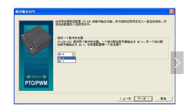
1. Configure the PTO through the command wizard
STEP7-Micro/WIN provides a position control wizard that allows the user to easily configure the PTO, PWM or Position module. The wizard can generate position-controlled instructions that can be used to dynamically control speed and position in the application.
This section controls the application of a stepper motor through PLC, and explains the specific operation process of PTO control stepper motor by using STEP7-Micro/WIN position control wizard.
Phone Holder,Phone Holder For Mobile Phone,Car Air Vent Phone Holder,Mobile Phone Holder
Shenzhen ChengRong Technology Co.,Ltd. , https://www.laptopstandsuppliers.com