The digital voltmeter based on CPLD is designed. CPLD device is used as the core processing circuit. It can be controlled by single-chip microcomputer, which can reduce external interference and improve resolution. The digital voltmeter automatically converts the range to improve the performance of the digital voltmeter.
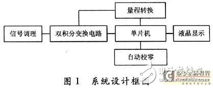
1 Scheme Argumentation and ComparisonThe double integral A/D is to integrate the input sampling voltage and the reference voltage twice to obtain a time interval proportional to the average value of the sampling voltage, and during this time interval, the counter is used to count the CP, and the output of the counter is The corresponding number of digits. The double integral A/D has the advantages of high precision, strong anti-interference ability and good stability, but the conversion speed is low, so it is suitable for instruments with high precision such as digital DC voltmeter and low conversion speed. The system block diagram of the design is shown in Figure 1. To achieve this system function, the following two options are available.
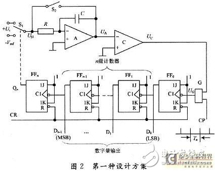
1.1 Option 1
The N-bit binary asynchronous addition counter is constructed by a JK flip-flop, and a falling edge flip-flop FF is employed. However, since the number of JK flip-flops is related to display accuracy, if the display precision is high, the number of flip-flops required is large, which requires a large amount of space and is susceptible to interference. If the minimum resolution of the 2 V file is 0.1 mV, then 2/(2n-1)=O. 1 mV, n ≥ 15, here take n = 16, as shown in Figure 2.
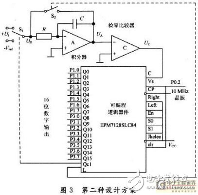
1.2 Scheme 2
The EDA programmable logic device integrates the counter and control circuit composed of 16-bit JK flip-flops into the system, which not only eliminates external interference, reduces measurement error, but also saves space and improves system response speed. CPLD is easy to use, fast, and cost-effective, as shown in Figure 3.
Comparing the performance of the two schemes, this design uses Option 2.
2 system design2.1 Hardware Part
2.1.1 Filter circuit
The filter circuit uses a voltage-controlled second-order low-pass filter, as shown in Figure 4. The op amp uses the low-temperature drift high-precision op amp OP07, taking R1=R2=R=1.592 kΩ, C1=C2=10μF, then f0=10 Hz.
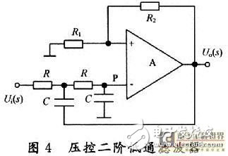
The transfer function is:

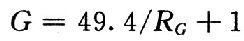
When Aup "3, the circuit can work normally and does not generate self-oscillation. make:

Then the voltage amplification factor:

The amplification factor for the DC signal is:
2.1.2 Measurement amplifier
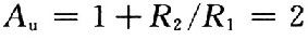
The measuring amplifier is shown in Figure 5. The AD620 is a low power, high precision instrumentation amplifier with a gain of:
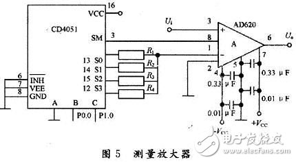
G can be adjusted by adjusting the size of the resistance between pins 1, 8.
For signals of different sizes, the MCU selects the resistors R1, R2, R3, and R4 through the 8-to-1 analog switch CD4051 to achieve different gain values. Divide 0.1 mV to 2 V into 4 ranges, ie 0.1 to 2 mV, 2 mV to 20 mV, 20 to 200 mV, 200 mV to 2 V, respectively, to enlarge by 1000, 100, 10, 1.1 times. , then R1=49.45 Ω, R2=499 Ω, R3= 5.489 kΩ, R4=494 kΩ.
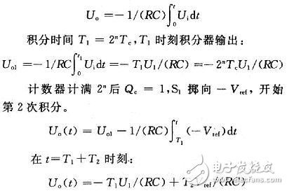
2.1.3 Double integral conversion circuit
The double integral conversion circuit is shown in Figure 3.
(1) Integrator: It consists of R, C and op amp. It integrates the input voltage and the reference voltage respectively, and its input is connected to the AD620 output.
(2) Zero comparator: The inverting terminal of the op amp is connected to the output UA of the integrator; the op amp is grounded at the same phase. When UA
(3) Programmable logic device: EPM7128 is a CPLDMAX7000S series device with internal memory and no external connection. Internally, it is a gate switch, a 16-bit counter, a 16-bit data register, and an auxiliary trigger. The gate switch controls the counter to start counting; the counter is used to count the CP pulse and trigger the auxiliary trigger; the register registers the counter value and waits for the microcontroller to read; the auxiliary trigger controls the integration of the sampled voltage and the reference voltage by controlling S1. The microcontroller controls the CPLD through Vs.
At the first integral sampling, Qc=O, control S1 is thrown to the input voltage Vi, L=0, control S2 is turned off, and the capacitor is discharged. The integrated output voltage is:
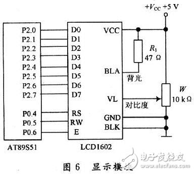
2.1.4 Display Module
The measured voltage value is displayed by the CAl602A liquid crystal module. CAl602A character LCD is a liquid crystal display with 5&TImes; 7 dot matrix graphics to display characters. It has low power consumption, small size, easy to use with decoding and driving circuit, and human interface is also very intuitive, as shown in Figure 6.
2.2 Software section
2.2.1 Software Flow Chart
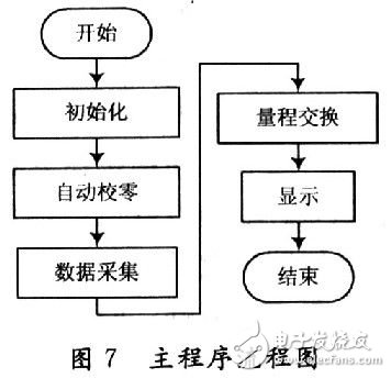
(1) The main program is shown in Figure 7.
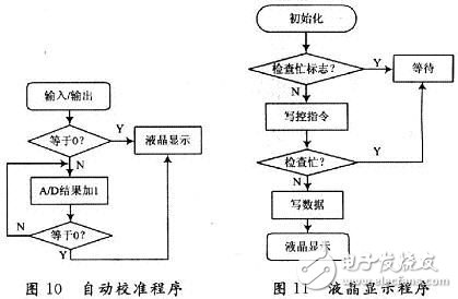
(2) The subroutine includes range conversion (see Figure 8), data acquisition (see Figure 9), automatic calibration (see Figure 10), and liquid crystal display (see Figure 11).
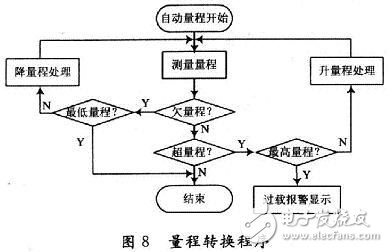

Range conversion:
When BC=01, 1~20 mV file, zoom in 100 times;
When BC=10, 20~200 mV file, zoom in 10 times;
When BC=11, 200 mV to 2 V, double the magnification.
3 system testing and analysis
3.1 Test Tools
The test tool includes the GOS-6031 30 MHz dual trace oscilloscope, the Agilent 34401A 6-digit half-digit voltmeter.
3.2 Test results
3.2.1 integral waveform output
No significant distortion was found after testing adjustments.
3.2.2 Voltage measurement
The calibration was performed using a 6-digit half-voltmeter. The results are shown in Table 1.
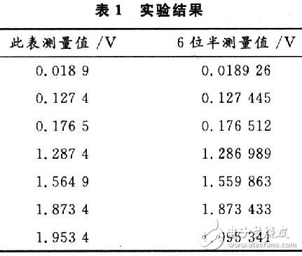
It can be seen from the above data that the design has completely reached the error of less than or equal to O. 05% ± 5 words and resolution is O. 1 mV requirement.
4 ConclusionThe design achieves the required functions well, and from the test results, the measurement error is small and the resolution is high. Due to the adoption of CPLD, environmental interference is greatly reduced. Of course, there are still some areas for improvement in the design, such as the ability to add automatic zero calibration.
Smart Phone Holder For Car Vent
Smart Phone Holder For Car Vent,Air Vent Iphone Mount,Air Vent Phone Holder,Air Vent Cell Phone Pouch Holder
Ningbo Luke Automotive Supplies Ltd. , https://www.nbluke.com