Electromagnetic Interference The interference signals generated by electronic devices in EMI are transmitted through wires or a common power line. Interference is called conducted interference. Conducted interference to many electronic engineers to bring confusion, how to solve the conduction interference? Find the right way, you will find that the conduction interference is actually very easy to solve, as long as the increase in the number of sections of the EMC filter in the power input circuit, and appropriate adjustment of each section filter The parameters of the device can basically meet the requirements. The organizer of the 7th Circuit Protection and EMC Symposium summarized eight strategies to solve the problem of conducting interference.
Countermeasure 1: Minimize the effective area of ​​each loop
Conducted interference points differential mode interference DI and common mode interference CI two. Let's take a look at how conductive interference occurs. As shown in Figure 1, the loop current produces conducted interference. There are several loop currents inside. We can think of each loop as an induction coil or the primary and secondary of a transformer coil. When a current flows in a loop, an induced electromotive force is generated in the other loop. , which creates interference. The most effective way to reduce interference is to minimize the effective area of ​​each loop.
Countermeasure 2: Screening, reducing the area of ​​each current loop, and the area and length of live conductors
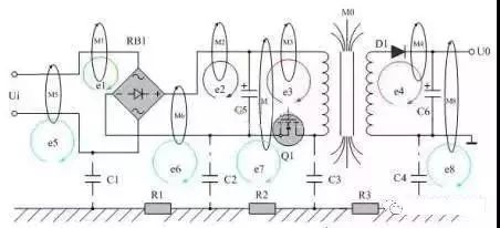
figure 2
As shown in Fig. 2, e1, e2, e3, and e4 are differential mode interference signals induced by the magnetic field to the loop; e5, e6, e7, and e8 are common mode interference signals generated by the magnetic field to the ground loop. One end of the common-mode signal is the entire circuit board, and the other end is ground. The common terminal in the circuit board cannot be regarded as grounding. Do not connect the common terminal to the enclosure unless the enclosure is connected to the ground. Otherwise, the common terminal and the enclosure will increase the effective area of ​​the radiating antenna, and the common mode radiation interference will be more serious. . One method of reducing radiated interference is shielding, and the other is to reduce the area of ​​each current loop (magnetic field interference), and the area and length of live conductors (electric field interference).
Countermeasure 3: Magnetically shield the transformer and minimize the effective area of ​​each current loop
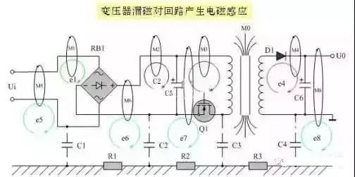
image 3
As shown in Fig. 3, among all electromagnetic induction disturbances, the interference caused by transformer leakage inductance is the most serious. If the leakage inductance of the transformer is regarded as the primary of the induction coil of the transformer, the other loops can be seen as the secondary of the transformer. Therefore, in the loop around the transformer, disturbance signals will be induced. One way to reduce interference is to magnetically shield the transformer and, on the other, to minimize the effective area of ​​each current loop.
Countermeasure 4: Use copper foil to shield the transformer
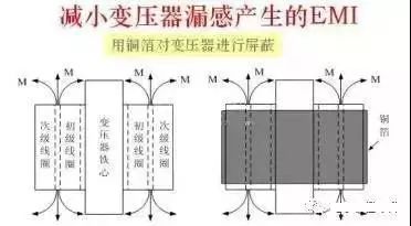
Figure 4
As shown in Fig. 4, shielding transformers is mainly to reduce electromagnetic induction interference caused by transformer leakage magnetic flux to surrounding circuits, and to generate electromagnetic radiation interference. In principle, non-magnetic materials do not directly shield the leakage flux, but the copper foil is a good conductor. When the alternating leakage flux passes through the copper foil, eddy currents are generated, and the direction of the magnetic field generated by the eddy currents. Just in the opposite direction of the leakage flux, some of the leakage flux can be cancelled out. Therefore, the copper foil can also play a good role in shielding the magnetic flux.
Countermeasure 5: Adopt two-wire transmission and impedance matching
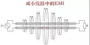
Figure 5
As shown in Fig. 5, two adjacent conductors, if the currents are equal in magnitude and the directions of the currents are opposite, the magnetic lines they generate can cancel each other out. For circuits with severe interference or relatively easy to be disturbed, try to use dual-line transmission signals instead of using common ground to transmit signals. The smaller the common ground current is, the smaller the interference is. When the length of the wire is equal to or greater than a quarter wavelength, impedance matching must be considered in the transmission signal line, unmatched transmission lines generate standing waves, and strong radiated interference to surrounding circuits.
Countermeasure 6: Reduce the area of ​​the current loop
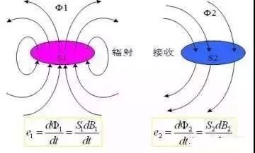
Figure 6
As shown in Figure 6, the magnetic field radiation interference is mainly generated by the magnetic flux flowing through the high-frequency current loop to the receiving circuit. Therefore, the area of ​​the high-frequency current loop and the area of ​​the receiving loop should be minimized. In the formula: e1, Φ1, S1, and B1 are the electromotive force, magnetic flux, area, and magnetic flux density respectively generated in the radiation current loop; e2, Φ2, S2, and B2 are the electromotive force, magnetic flux, and area generated in the radiation current loop, respectively. Magnetic flux density.
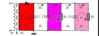
Figure 7
The following is a schematic diagram of FIG. 7 to explain the current loop radiation. As shown in the figure, S1 is the rectification output filter loop, C1 is the energy storage filter capacitor, and i1 is the loop high-frequency current. This current is the largest in all current loops, and the magnetic field generated by it is the most serious. The area of ​​S1 should be reduced as much as possible. . In the S2 loop, there is basically no high-frequency loop current, ∆I2 is mainly the ripple current of the power supply, and the high-frequency component is relatively small, so the area size of the S2 basically does not need to be considered. C2 is an energy storage filter capacitor, which provides energy specifically for load R1. R1 and R2 are not simple load resistors, but are high frequency circuit loads. High frequency current i3 is basically provided by C2. The position of C2 is relatively important. The connection location should be considered to minimize the S3 area. There is also a ∆I3 in S3. It is mainly the power supply ripple current, and there is also a small amount of high-frequency current components. In the S4 loop, there is basically no high-frequency loop current. The ∆I4 is mainly the ripple current of the power supply. The high-frequency component is relatively small, so the area of ​​the S4 basically does not need to be considered. The condition of the S5 loop is basically the same as that of the S3 loop, and the current loop area of ​​the i5 should also be as small as possible.
Solution 7: Do not use multiple loops in series
Several current loops in FIG. 7 are connected together in series to supply power, and it is easy to generate current common mode interference, especially in a high frequency amplification circuit, which generates high frequency noise. The causes of current common-mode interference are: ∆I2 = ∆I3+ ∆I4+ ∆I5
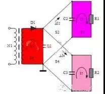
Figure 8
In Fig. 8, each current loop is separated from each other and is supplied in parallel. Each current loop is independent and no current common mode interference occurs.
Countermeasure VIII: Avoid interference signals in the circuit to generate resonance
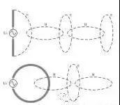
Figure 9
As shown in Figure 9, one pole of the common-mode antenna is the entire circuit board and the other is the ground wire in the connection cable. The most effective way to reduce radiated interference is to shield the entire circuit board and ground the enclosure. The reason for the radiation interference of the electric field is that the high frequency signal charges the conductor or the lead, and the length and the surface area of ​​the conductor should be minimized. The reason for the magnetic field interference is that high-frequency current flows through the conductor or loop, and the length and area of ​​the current loop in the circuit board should be minimized. The higher the frequency, the more severe the electromagnetic radiation interference; when the length of the carrier fluid can be compared with the wavelength of the signal, the interference signal radiation will be enhanced. When the length of the carrier fluid is exactly equal to an integral multiple of one-quarter wavelength of the interfering signal, the interfering signal will generate resonance in the circuit. At this time, the radiation interference is the strongest, and this situation should be avoided as much as possible. See here, do you feel that this eight-step walk, conducted interference in the master? Finally attached a variety of interference pulse waveform for your reference (Figure 10). Any non-sinusoidal wave can be seen as a very large number of signals with different rising and falling rates (or sine waves of different frequencies) superimposed on each other. The intensity of electromagnetic radiation is proportional to the rate of change of voltage or current. The spectrum of various interference pulse waveforms:
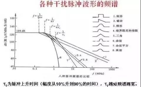
Figure 10 (Cynthia)
Dual Fuel generator assembly by dual fuel engine, alternator, radiator, controller, base frame;
. Dual Fuel engine brand: CRRC, CSSC, CSI, SWT
. World famous AC alternator brand: Stamford, Leroy Somer, Mecc Alte, Marathon, Faraday, SWT
. World famous genset controller brand: Deepsea, ComAp, Deif, Heinzmann, Woodward
. Gas Control System: Ignition system, Gas Throttle System, Ga Mixer System, Gas Train Valve System
. Start Battery system
. Optional for Remote Cooling system with CHP & CCHP Control
. CHP- Combine with Heat and Power Electrical system
. Maximum 80% Natural gas, 20% Diesel fuel
.CCHP- Combine with Cold, Heat and Power electrical system
Dual Fuel Genset,Dual Fuel Generator,Dual Fuel Power Plant,Diesel & Gas Generator
Guangdong Superwatt Power Equipment Co., Ltd , https://www.swtgenset.com