The longer the filter, the better? The times we live in admire "the bigger the better", but this wisdom may not apply to the length of the FIR filter.
The filter length supported by the DSP is usually 1024 tabs, some up to 4096 points. Why don't people want or need longer FIR filters? If a manufacturer introduces an 8192-point FIR filter in a DSP, would people choose to discard competing products and choose it?
The lower the frequency, the longer the timeFirst of all, we need a file for practice and experimentation. The measurement data of the speaker can be used, but a slightly simpler file is easier to help us find important points.
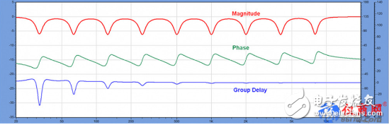
See Figure 1 for reference. I created this series of lifting filters (a separate symmetric equalizer with an octave bandwidth) in FIRCapture software and saved it as a WAV file. This response can be easily created with any 9-segment parametric equalizer.
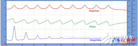
I chose Q=6 to minimize the overlap between filters. This set of filters, in turn, constitutes a filter that does not have the same response as the speaker, let alone the high-pass and low-pass responses that are necessary at the highest and lowest frequencies. If this is the response of a loudspeaker (let's assume this), we will want to balance the raised parts to get a flatter overall response. Through this document, we can well examine the frequency resolution of the FIR filter.
The frequency domain view shows the amplitude, phase, and group delay of the frequency response. Please note that phase and group delay are two different ways to show how the filter changes its time behavior when the signal passes through. Since the phases are relative, the phase behavior of each bump is the same.
In my previous article I demonstrated that the minimum phase response of a bandpass filter is first in the positive direction, then returned to the origin at the center frequency of the filter, and finally the negative direction. This phase shift will cause frequency-dependent ringing of the signal passing through the filter. The duration of the ringing phenomenon is shown by the group delay graph.
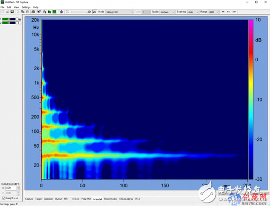
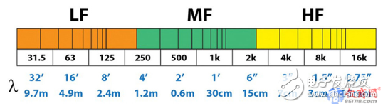
Figure 2 is a frequency/time domain synthesis diagram of the filter. Figure 3 shows the wavelength of the center frequency of each separated octave. What is the relationship between the two? Since the speed of sound is about 1 foot/millisecond (ft/ms), the center frequency wavelength of each octave is approximately equal to the time required for one cycle. The concept of wavelengths shows that the sound waves are related to time and space in a very visual way, and the filter response is also the same.
The group delay (GD) is proportional to the frequency of the filter. The lower the frequency, the longer the group delay. From the name alone, it seems to refer to the delay caused by the signal passing through the filter, which is somewhat misleading. The storage property of the filter causes a ringing phenomenon, that is, an extra cycle is added to the signal.
The group delay shows how long the lift filter occupies. It is not surprising that low-frequency bumps have long ringing. The group delay is inversely proportional to the filter frequency (proportional to the wavelength). When the phase offset is equal, the lower the frequency, the longer the group delay.
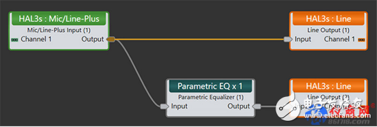
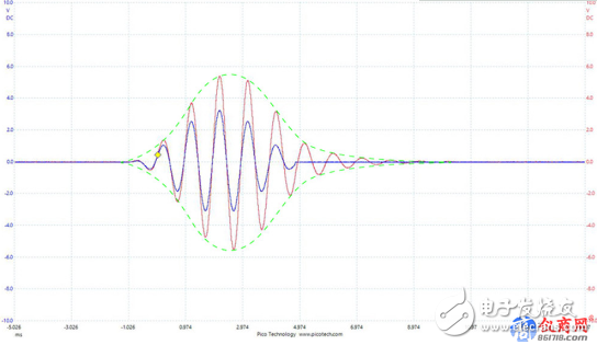
For demonstration purposes, we use the signal processing link shown in Figure 4 as an example. We enter a test signal to see what will happen. Figure 5 shows the results of a 2-channel oscilloscope. The blue locus is a wavelet of 1000Hz 6.5 cycles. This is one of the Don Keele test signals. The red trace is the result of passing this signal through a 1000 Hz boost filter. Please note that the original signal and the signal processed through the filtering are in phase, but the signal period through the filter increases. This is the ringing phenomenon observed in the time domain. A ringing reduction filter will occupy the same amount of time.
How does an analog or digital IIR filter correct the response? It must be in the opposite amplitude and phase offset to the bump. Because the IIR filter is cyclic, it uses feedback to return a portion of the output signal back to the input for reprocessing (similar capacitance charging and discharging).
Therefore, the IIR filter does not have a low frequency limit during operation (at least when compared to a FIR filter) and does not cause significant processing delays. As long as there is an input signal, there will be an output signal, and the impulse response of the filter (theoretically) will never decay to zero.
The forward group delay is the sign of the narrow band boost filter (Figure 1), and the negative group delay is the sign of the cut filter. Figure 7 shows a set of IIR filters implemented with a popular DSP EQ module. By comparing the amplitude and phase of each of the bumps of FIG. 1 and each of the notches of FIG. 7, it can be found that the equalizer of FIG. 7 can completely correct the response of my file.
Incidentally, the group delay of the narrow band signal does not represent the signal delay, but it shows the duration of the ringing phenomenon of the filter. Some of the audio terms are not literal meanings, such as "constant voltage", but this is another topic and will not be repeated here.
Minimum phase FIR EQLet's discuss the minimum phase FIR below. Its response can be exactly the same as the IIR filter generated by the parametric equalizer. The key difference is that the response of the FIR filter is completely independent of the drive signal. It is a finite length impulse response with frequency resolution related to length.
Since T = 1/F, the lower the frequency to be affected, the longer the required filter length (time span, more number of points). Correcting low-frequency bumps requires the introduction of amplitude and phase conjugates at each frequency, which is also conjugate to the group delay. This is a very long time span for low frequency bumps.
Look back at Figure 1. Since this filter is the minimum phase filter, the processing delay is very small, similar to that of the IIR filter. The difference is that the bandwidth of the FIR filter is determined by its length (Figure 6), so a very long filter is required to equalize the low frequency bumps. This is independent of the processing algorithm used to create the filter.
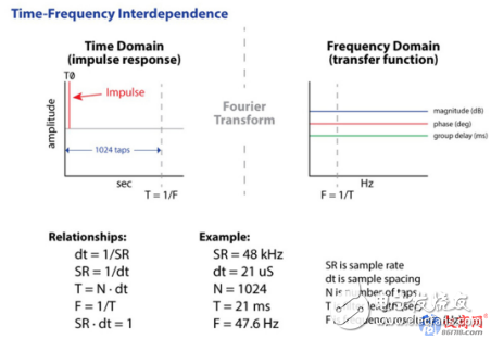
As can be seen from Figure 6, a 1024-point, minimum-phase FIR filter with a sample rate of 48 kHz is 21 milliseconds in length. Since T=1/F, the frequency resolution of this filter is 47.6 Hz.

What does this mean? This means the spacing between each data point in the frequency domain view.
It also represents the lowest frequency that the filter can affect. In fact, the frequency resolution is even lower (the lowest frequency that can be affected is slightly higher) because it often takes several cycles of the waveform to determine a certain frequency.
If you add more points? Double the filter length will double the frequency resolution so that the frequency interval between the data points becomes 24 Hz.
It also makes the low-frequency limit dive to half, go to 24Hz. This trend will continue and each doubling of the number of points will cause the filter's response to dive to an octave. Therefore, a longer FIR filter will make: 1) The filter spread to lower frequencies. 2) The frequency response of the filter presents more detail because the data points are more dense.
In the case of the minimum phase FIR filter, more number of points is of great benefit because it means that the filter can be extended to lower frequencies. Since this is the minimum phase filter, there is no additional processing delay compared to the IIR filter. To get a smooth response from my model file, it takes about 4096 points, which is far more than the number of points that can be supported by the existing DSP. This makes the argument that more points are needed become more and more intensified.
Don't worry about the conclusionLet us seriously consider. The minimum phase FIR behaves like the minimum phase IIR filter except that it requires a sufficient number of points to affect the lowest frequency to be achieved. Low frequency equalization requires a longer filter length.
But why create a minimum phase filter in a DSP through a FIR filter module that consumes a lot of system resources? A carefully tuned Parameter Equalization Module (IIR) will take up much less system resources, but produce the same smooth response with better frequency resolution (Figure 7). Using the fewest possible system resources to achieve the desired results is a best practice in the audio industry, and using FIR filters for minimum phase equalization is not efficient.
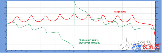
Let us consider the case where the corrected response is not the minimum phase. In my reference, I added a second order all-pass filter (500 Hz) to the response (Figure 8). This will cause a phase shift in the entire bandwidth of the filter but will have minimal effect on the amplitude response. In fact applications, this all-pass behavior may stem from the use of a crossover network. The minimum phase FIR filter cannot compensate for such additional phase offset.
A linear phase FIR has a symmetrical impulse response and the main signal arrival time is in the middle of the impulse response (IR) (Figure 9). We set the arrival peak to relative time zero, before which the time span provides a "negative time" arrival for energy arrival after the conjugate master reaches the peak.
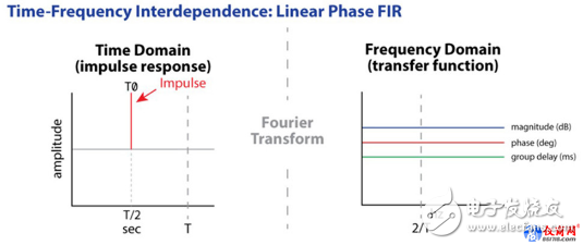
There is a causal relationship between these "pre-delay" and factual time, but there is no causal relationship with the main information arrival time. This allows the filter to compensate for reflected energy by the opposite "negative time" response.
So, if the bit length is 1024 points, the linear phase FIR filter will place the main arrival time at T/2, allowing half of the filter length to provide the pre-arrival time for post-arrival energy generated by the conjugate loudspeaker or room. It also allows the introduction of the required negative group delay to compensate for the divider's all-pass response.
Because half of the filter length is used for "negative time" correction, the frequency resolution of the filter will be halved. For example, the 1024-point minimum phase FIR filter has a frequency resolution of 47.6 Hz. The same length of the linear phase FIR filter has a frequency resolution of 95.2 Hz because half of the length is reserved for phase equalization.
The more points, the better?This seems to be the case for the minimum phase FIR filter. The problem is that the non-minimum phase filter needs to reserve half the length for phase equalization. This will appear as a processing delay (often mistakenly referred to as delay). Unlike the minimum phase FIR filter, as the length of the linear phase FIR filter increases to increase its frequency resolution, its delay increases. This is not caused by the speed of the DSP, but from TF = 1.
Now call my reference file again, but this time it is a series of reduction filters, the frequency of which is the same as the original lifting filter (Figure 10). From the previous discussion, the group delay view (blue line) shows the length of the ringing of the filter. Please note that it is now negative, but this only means that the phase shift generated by this filter will continue to increase throughout the entire bandwidth. It does not mean that there is a "time advance" or the filter response is non-causal.
What can't be avoided is that the lower the frequency, the longer it will take for the filter to take effect. At the lowest center frequency of the octave (31.5 Hz) this time will become very long (~40 ms). For live performances and many fixed installation applications, such long processing delays are unacceptable. A 1024-point FIR filter (48 kHz sample rate) has a duration of 21 milliseconds, which means that the processing delay is approximately 10.5 milliseconds.
Increasing the sampling rate to 96 kHz does not reduce the processing delay because the number of samples that must be processed is also doubled. The fact that it cannot be changed is that the minimum length of 21 milliseconds can only affect 48Hz, and the actual frequency resolution is 3 times that of 48Hz, or 150Hz.
The problem gets worseLinear phase FIR filters have another drawback. Since "relative time zero" is in the middle of the filter duration, its frequency resolution is half that of the minimum phase FIR filter.
Therefore, if a 1024-point minimum-phase FIR filter can affect 150 Hz at a minimum, a 1024-point linear-phase FIR filter can only affect 300 Hz at the minimum.
The frequency of the effect to submerge to 150 Hz will require a 2048-point filter, meaning that the processing delay will also have to double from 10.7 milliseconds to 21 milliseconds.
For my example file, an 8196-point FIR filter will be needed to smooth out the entire passband response. The required processing delay is approximately 85 milliseconds.
On the surface, the longer the length of the FIR filter, the benefit seems to be to increase the frequency resolution so that: 1) it affects lower frequencies. 2) Include more details on the entire bandwidth.
I have shown that, at least for linear phase FIR filters, affecting lower frequencies (more number of points) will increase the processing delay. This is not due to lack of processing power, but from the correlation of time and frequency. The low frequencies last longer and occupy a lot of space. Digital processing cannot change this situation.
Part of the benefitsThere are a total of 10 octaves in the audible spectrum, so each octave takes up one tenth of the whole (logarithmic scale). Double the filter length, which will double the processing delay, which only makes you one-tenth of the spectrum that you are equalizing.
It's like doubling the amplifier's power just to get a 3dB boost. Sometimes it's a tipping point, with very little reward, and it's not worth it. In the case of a power amplifier, the price is money, and for a linear phase FIR filter, the cost is a delay. It can be said that the digitally processed currency is time. You can get good results if you can wait long enough.
In most rooms, the lowest two octaves (sub-low frequencies) are below the Schroder frequency curve, and room modes have a profound effect on the frequency response of each seat. Even if we pass a linear-phase FIR filter to treat the response of a certain point in the room as “perfect†and the response in other seats is different, what is the significance of doing so?
Does that require higher filter accuracy? A 1024-point filter, the frequency interval between data points is about 48Hz. If this is not enough to correct your frequency response, chances are that you are trying to correct something that should not be resorted to equalization at all, such as comb filtering due to room reflections. The more "details" in the frequency response, the more time response is "position dependent," because these details are caused by reflections from different surfaces.
For mobile test microphones, the response changes greatly. A very precise FIR filter is only suitable for "correcting" a point in space. This may be suitable for echo cancellation of the conference system at a particular microphone position, but this does not benefit the entire viewer area. Longer FIR filters do not make much sense for field applications.
Is higher sample rate helpful?Purely rumors. Unfortunately it is not. Returning to Fig. 6, the filter time interval dt = 1/SR (sampling rate) is multiplied by the number of points (N) to obtain the filter length (T). The frequency resolution (F) is 1/T.
This is a simple relationship and shows that if the sampling rate is doubled, the filter's frequency resolution will be reduced by half. We made the problem even worse! If the sampling rate is doubled, then the number of samples to be processed is multiplied by 2, so that the filter length must be doubled to maintain the same frequency resolution.
Let us examine the opposite situation. Halving the sampling rate will increase the filter's frequency resolution. However, to sacrifice high-frequency response, it can only be extended to SR/2. The Nyquist-Shannon theorem cannot be denied.
All this does not change the processing delay required by the linear phase FIR filter, which is half of the filter duration. Higher (lower) sample rates cannot change the time, frequency, or wavelength of the signal.
in conclusionThere is no doubt that with the development of technology we will have longer digital filters in the future. The chip is constantly improving, as is the use of chips. We may recall that 16-bit/44.1 kHz "CD-grade" audio was once almost impossible to achieve. However, many people today think it has a low resolution. The FIR filter will also develop along this trajectory.
But there are some obstacles to implementing a longer filter, which is technology-independent. I have shown in the above article that the main hurdle is the processing delay, which is related to the length of time the filter must affect (see Figure 1).
In a live sound system, we can only tolerate a little delay. This standard is not very accurate, but most people will agree that the filtering process of more than 20 milliseconds is a relatively long time. This unavoidable processing delay increases the latency of other digital devices in the signal chain, typically by an additional 10 milliseconds. In time, we have to give up on the linear phase equalization of low frequencies, at least for field applications.
Applying a linear phase FIR filter to high frequencies and a minimum phase FIR filter to low frequencies seem to be a solution. This is called a "mixed-phase" filter and I think this will be the future trend. Some people began to think IIR filters were useless, but it is undeniable that they have the widest bandwidth, the lowest processing delay and use less system resources than any other digital filter. Please do not take away my parametric equalizer module!
The number of points cannot be infinitely high, which means that we must think about what is the focus of correction and the reasons behind it. Just like a spoonful of peanut butter left in the jar, we must make good use of it. How does my balanced processing affect the entire coverage area of ​​the speaker, not just the "golden location" of the test microphone? If one considers multiple seats, the magic halo of a linear phase FIR filter will fade quickly.
Using a 1024-point FIR filter is better than using a longer-length filter. Human cognition places reasonable limits on the sampling rate and bit depth required for analog-to-digital conversion, and the time, frequency, wavelength, and delay also limit the benefits that a longer FIR filter can provide. In the audio industry, making things bigger is always open to question, and digital filters are no exception. This is not a bad thing, it can be balanced, and it can lead people to think whether it is a pursuit of really producing a good voice or whether the data in the specification table is better.
This explains "less is more".
French Power Strip,Surge Protector Power Strip,Power Strip With Flat Plug,Overload Protector Power Strip
CIXI KYFEN ELECTRONICS CO.,LTD, , https://www.kyfengroup.com