The high-pass filter occupies an important position in the filter circuit. It can be combined with a low-pass filter to form an ultra-wideband filter, and it can also constitute a frequency divider connected by a passband. Ultra-wideband absorption filters also need to use this. Devices. Filters with other structures can find a lot of reference materials in textbooks and websites, but broadband high-pass filters rarely see simple and efficient design methods. Here we use a 2GHz ultra-wideband high-pass filter example to illustrate the suspension line high-pass filter. Filter design principles and methods.
1. Common types of high-pass filtersCommon high-pass filters have the following types, as shown in Figure 1:
· Distribution parameters parallel short circuit stub type:
Detailed introduction to "Microstrip Filters for RF/Microwave ApplicaTIons"
· Semi-concentrated parametric type (suspension line high pass / finger capacitance, etc.)
Less effective articles, this article focuses on
Broadband bandpass type (bandpass broadband structure such as cross finger)
Reference bandpass filter design method
· Waveguide type (waveguide natural is Qualcomm)
Figure 1, common high-pass filter structure
2. Design challenges and countermeasures of suspended high-pass filters1) The design challenge of the suspension high-pass filter
The suspended line high-pass filter is a semi-lumped parametric filter, which in all forms of high-pass filters can achieve the highest bandwidth up to 20 octaves.
A typical high-pass circuit is shown in Figure 2. When converting an ideal LC prototype into an actual physical structure, the parallel short-circuit inductor can be accurately represented by a transmission line, but how to accurately represent the series capacitance for the suspended line high-pass filter design It is a challenge. The core of this article is also here.
Figure 2. Typical high-pass prototype and actual model
2) Design measures for high-pass filter of suspended wire
The first time I made a suspension line high-pass filter, I tried to use the following methods. These methods are also sub-consciously thought by practitioners.
· Flat plate capacitance method to calculate the size of the suspension series capacitor
· Simulate the capacitance structure separately, and the parameter extracts the capacitance value
Although these methods are clumsy, they can be designed after many iterations.
In order to obtain a highly efficient model, through reading the literature, it was finally found that the solution was based on the most basic transmission line theory, as shown in Figure 3. The series capacitance of the suspended line is a coupled microstrip line and the model describing the coupled microstrip line can accurately describe the structure. When we design the high-pass filter, the odd-mode impedance and length of the desired coupled line can be calculated by the equivalent principle of Fig. 3, and by the odd-mode impedance we can determine the size of the coupled microstrip line. At the same time, the influence of the even-mode impedance on the filter performance can also be identified in advance through circuit simulation.
If you are interested in filter design, it is recommended that you carefully study and understand the coupled-line model. Recommended bibliography "modern filter structure and design" or "microstrip circuit."

Figure 3. Accurate description model for series capacitors
3, the design of suspended line high-pass filter1) Design steps
The suspended line high-pass filter follows these steps:
a) Analysis of indicators, selection of a reasonable structure based on the periodicity of the transmission line and other requirements of the filter
b) A coupled-line high-pass model is used in ADS to obtain an accurate three-dimensional electromagnetic simulation model
c) Electromagnetic simulation in Sonnet or HFSS to verify the optimization model
2) Design Example
a) Analysis of indicators and selection of rational structure
In general, it is necessary to analyze the bandwidth, volume, power capacity, filter order, and whether zero out-of-band is required to select the proper structure and size. Here as a method to explain, choose a relatively simple model, omitting the indicator analysis steps.
b) Establish high-pass model in ADS to obtain accurate 3D electromagnetic simulation model
According to the analysis in Section 2, the series capacitance C = 1/2 * Yotan θ can determine the basic size of the coupled microstrip line. Since personal habits are used in the ADS optimization method, detailed calculations are not performed here and interest can be deduced on their own. The basic parameters of the suspension line according to personal habits are shown in Table 1. Detailed calculation shown in Figure 4
Table 1, key physical dimensions of the suspension line
physical
Size Upper and Lower Air Cavity High Dielectric Thickness Dielectric Constant Coupling Microstrip Line Width Parallel Inductor Thinnest Line
1mm0.127mm2.942mm0.2mm
3mm coupled line parameter parallel maximum impedance
theory
Data ZeKeZoKoZHKh
114.541.036.182.711551.03
Figure 4. Calculation of key dimensions
By obtaining the above key parameters, the suspension high-pass model shown in FIG. 5 is established in the ADS. By tuning and optimizing the length of each transmission line, the model achieves a theoretical response.

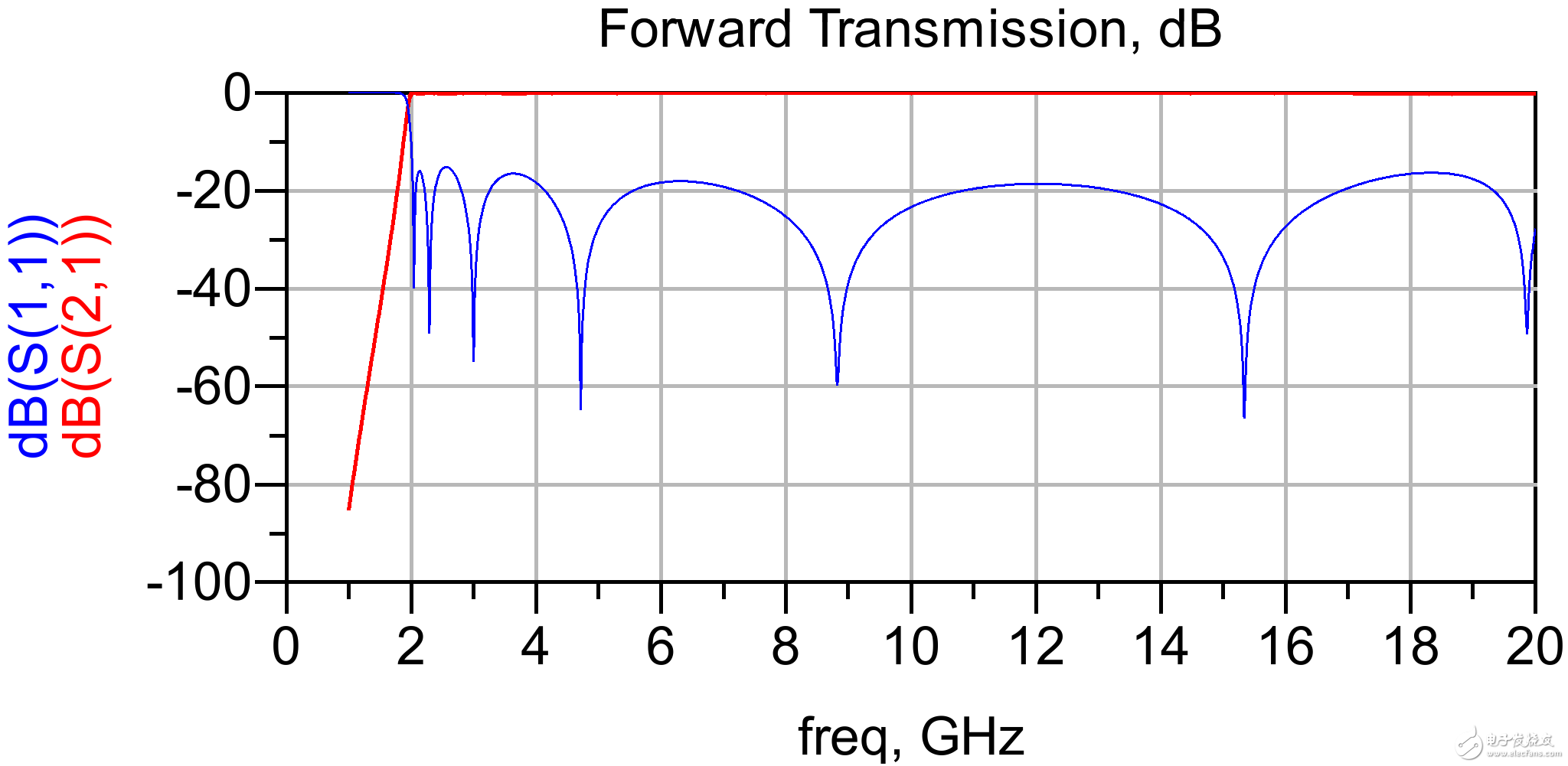
Figure 5. Hanging line high-pass model in ADS
c) Sonnet electromagnetic simulation verification
According to the above circuit simulation, the actual physical dimensions of the coupled transmission lines and the parallel short-circuit transmission lines are obtained. A high-pass model shown in FIG. 6 is established in the sonnet, and a simulation result is shown in FIG. 6 .
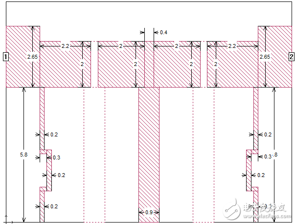
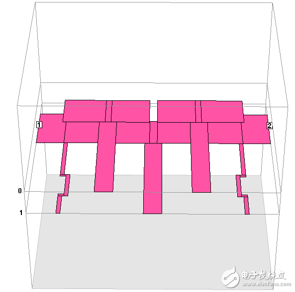
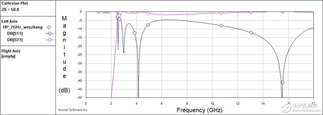
Figure 6. Electromagnetic simulation verification and one simulation result
Through simulation, we can see that the electromagnetic simulation results are very close to the theoretical design, which proves the correctness of this design method. However, the standing wave of electromagnetic simulation is poor, mainly because the following factors are not expressed in the model:
· T-junctions of series capacitors and shunt inductors are not expressed in the circuit model. Friends who pursue perfection can express T-junctions through S3P files.
· The fringe capacitance of the series capacitor is not expressed. It can also be expressed by the S3P file.
· There is mutual coupling between parallel short circuit stubs. This coupling is not expressed in the circuit. Due to space limitations, this problem will be specifically described in an article.
It has been proved that when the shunt short-circuited stub exceeds the gap of 0.5 mm, the circuit model can be accurate only when the T-junction and the fringe capacitance are expressed.
What suddenly appear into your mind when hear Mini Gaming PC? Is there quality heat-releasing fan and box design of Mini Gaming PC Build? Does it run stable and smoothly when handle heavier jobs, like Photoshop, Pr, engineering design and drawing, 3d Max, big games, etc. ? now we can be responsible to answer [ Yes". No matter cheap mini gaming pc or Mini Gaming PC Under $500, equips with quality fan to heat releasing. Therefore, no need to worry that again.
To processor, can do from intel celeron j4125, N5105 up to i3, i5 i7 10th 11th 12th with or without video graphics. To slots, same rich as traditional computer tower, like above 4 or 6 usb ports, 2 Rj45, VGA, PD, slot, etc.
You can also find Mini Gaming PC, j4125 Mini PC ,Custom All In One PC, windows 10 Education Laptop,Quad Core Processor Laptop, 15 Inch Gaming Laptop ,windows Yoga Laptop , 8 inch Android Tablet, etc.
If any other special requirements interest, you can also let us know, will try our best support you.
Meet your unique demand in this field is our mission, so just feel free contact us whenever you have different idea.
Mini Gaming PC Build,Cheap Mini Gaming PC,Mini Gaming PC Under $500,Mini Gaming Desktop
Henan Shuyi Electronics Co., Ltd. , https://www.shuyielectronics.com