Although loop analysis is an important means of detecting the stability of a control system, there are many details to be aware of during the test. How to quickly understand the meaning of loop analysis? How do you set parameters for loop analysis? How is the result of the loop analysis read? This article will answer you one by one.
First, how do you say three things in a loop analysis?
1. A stable and reliable system must be a closed loop system (with feedback). The controller designs an algorithm based on the deviation of the actual output of the system from the ideal output, so that the output value approaches the set value;
2. System stability needs to be quantified by the gain phase margin in the loop. This indicator can be measured by sweeping;
3. Loop analysis is to inject the interference signal of the frequency change in the control system to obtain the frequency response curve of the system.
In summary, loop analysis can tell if the performance of the control system is stable when the load is changed, it is as simple as that!
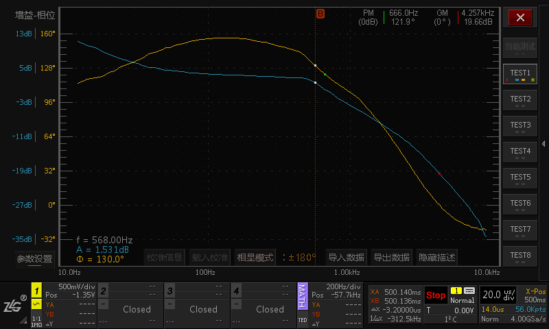
Loop analysis result picture
Second, what is the result of loop analysis?
The oscilloscope can obtain the Bode diagram (amplitude frequency characteristic and phase frequency characteristic) of the loop system according to the relationship between the output signal, the amplitude and phase of the input signal and the frequency. If you want to understand the stability of the product, it is not enough to rely on the brand, experience, and R & D personnel to shoot the chest. With the help of Bode diagram to assist quantitative analysis, one test will know!
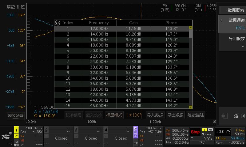
Loop analysis data report
Third, with loop analysis, what improvements in power performance?
The frequency analysis of the power supply can be quantified by loop analysis to optimize the power supply in a more stable direction. Engineers no longer have to try to accumulate experience through blind trials, and device selection does not require excessive consideration of margins, thus better controlling power costs.
Fourth, the key test steps and parameter settings of loop analysis
1, looking for interference signal injection points
In a voltage feedback type switching power supply circuit, the test signal injection point is between the sampling point of the feedback loop and the output voltage point. To distinguish the sampling points is relatively simple, just observe which branch of the output voltage is divided by the feedback voltage.
The injection resistance can be selected from 10 to 100 ohms. This resistance has little effect on the feedback circuit. It is recommended to reserve this resistor in advance when designing the system.
2, injection signal amplitude adjustment
The amplitude empirical value of the injected signal can be set to 5% of the output voltage. If the amplitude is not too small, the oscilloscope may not be able to recognize it; if it is too large, the system may be nonlinear and cause measurement distortion.
3, scanning frequency range setting
The cutoff frequency of the loop system is recommended to be set to 1/20 to 1/6 of the switching frequency. Within this range, the crossing frequency point of the loop can generally be found. Note here that the loop system crossover frequency should not be too low, otherwise the loop cannot respond to high frequency load fluctuations, causing noise of the output voltage.
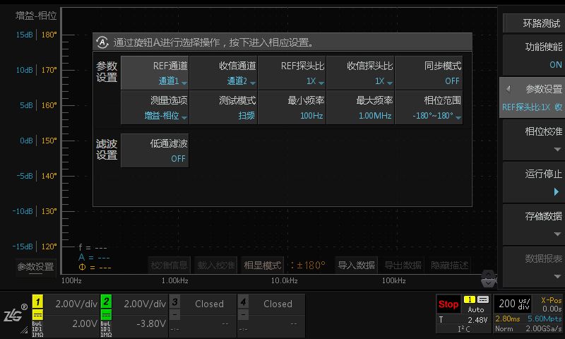
Loop analysis parameter setting interface
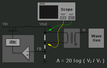
Fourth, the construction of the loop analysis and measurement system
In the application of the ZDS4000 loop analysis switching power supply, in addition to the oscilloscope, a signal generator module and a high voltage isolation transformer are required. The signal generator module is used to generate the injection signal (the ordinary signal generator can also be used instead), and the high voltage isolation transformer is used to isolate the influence of the injection circuit on the operation of the loop circuit.
Tip: Due to the weak amplitude of the injected signal, it is recommended to use the 1X attenuation probe test. If 10X is used, the signal is easily overwhelmed by noise after it is attenuated. Also use grounding springs when grounding, not grounding clips.
V. Interpretation of loop analysis sample data
Since the feedback of the closed-loop system of the switching power supply is relatively simple, the Bode diagram obtained by the loop analysis can be analyzed simply:
When the closed-loop gain is 0 dB, that is, when crossing the frequency, the phase margin generally needs to be greater than 45 degrees;
When the phase is close to 0 degrees, the closed loop gain should be less than -20dB.
If the above conditions are met, the closed loop is a stable system.
As shown in the figure below, the system has a phase margin of 135.5 degrees and a gain margin of 30db in the upper right corner of the screen.

Tempered Glass Screen Protector
The JJT Tempered Glass Screen Protective Film is protected by specially treated glass, and the Tempered Glass Screen Protector brings excellent scratch resistance to the screen. The Tempered Glass Protective Film is made of shockproof technology, which has the characteristics of anti-scratch, anti-fingerprint and anti-oil, which can greatly reduce the damage to the screen due to strong collision. The adhesive force of the silicon adhesive ensures that there is nothing between the screen protector and the screen, thereby improving touch sensitivity. Ultra-transparent glass can ensure a better clear image quality than ordinary Screen Protectors.
The surface hardness of the Tempered Glass Screen Protection Film is 9H, which is 4 times that of ordinary PET Film. Sharp objects (such as knives and keys) will not scratch the surface.
The Screen Protector has an "oleophobic and waterproof" coating to prevent fingerprints and other contaminants, making the screen protector easy to clean.
It has unparalleled touch and high responsiveness to touch, 99.9% transparency, transparent without bubbles.
Tempered Screen Protector, Tempered Glass Screen Protector, Tempered Glass Protective Film, Tempered Glass Film, Tempered Glass Screen Protective Film
Shenzhen Jianjiantong Technology Co., Ltd. , https://www.jjthydrogelmachine.com