Abstract: AC voltage peak detection is an important indicator in industrial power safety monitoring. It introduces a design of intelligent AC voltage peak meter measurement system based on Modbus-RTU communication protocol based on MSP430F449, MAX1270 and RS 485 bus hardware. And successfully applied to the peak detection of the AC voltage. The system is portable, low-power, and easy to connect with a computer or a controller that complies with the Modbus-RTU protocol, making it easy to set up a remote monitoring system.
Keywords: Modbus protocol; AC voltage peak; MSP430F449; MAX1270
This article refers to the address: http://
0 Introduction AC voltage peak refers to the maximum (positive peak) or minimum (negative peak) of the AC voltage, which is a very important parameter in industrial production. In order to ensure the safety of the electrical equipment, it is important to detect the peak value of the power supply voltage. The methods for measuring the peak value mainly include an oscilloscope method, an indirect calculation method, and a dedicated peak table method. Although the oscilloscope can visually display the waveform and peak value of the voltage, the oscilloscope cannot be used as a field monitoring device in terms of cost and portability; the indirect calculation method is only applicable to the standard sine wave, and the utility is not practical; the dedicated peak table mostly has a volume. Large, inconvenient to carry, and inconvenient to connect with a computer or control device. In response to the above shortcomings, the MSP430 series MCU, MAX1270 analog-to-digital converter, and the Modbus-RTU protocol have been used to successfully develop a low-cost, portable and intelligent peak meter device.
1 Measurement principle Since the fluctuation of the power supply grid and the voltage waveform of the grid are non-standard sine waves, the peak value cannot be calculated indirectly by the average value or the effective value. The system uses a non-standard sine wave to sample multiple times in one cycle, and compares the sampled values ​​by bubbling method to obtain the maximum or minimum value of the voltage as its positive and negative peaks. Obviously, as long as the sampling density is appropriate, the true voltage peak can be obtained. The frequency of the AC power in China is 50 Hz, and the sampling frequency in the design is set to 10 kHz, that is, 200 samples in each AC waveform period, which is enough to correctly reflect the voltage change and determine the peak value of the voltage.
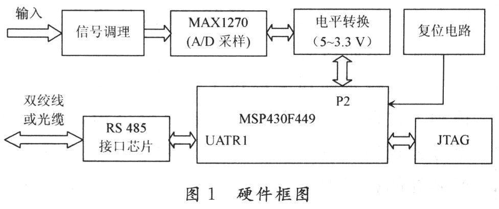
2 hardware design In the design, MSP430F449 single-chip microcomputer, MAX1270 analog-to-digital converter is the main device. The front-end A/D input uses the resistor divider method to step down the AC power; the RS 485 chip is used as the communication interface chip, and the hardware block diagram is shown in Figure 1.
2.1 A / D input conditioning protection circuit design Take 220 V AC as an example, the theoretical peak voltage is 311 V, but considering the grid fluctuations, sine wave distortion, etc., the voltage peak is likely to exceed 311 V, then according to the work For empirical and measured conditions, select a voltage value as the maximum possible voltage, assuming 500 V. If the input range of the MAX1270 is set to ±5 V, the divider ratio of the divider resistor should be set to 100:1. The voltage after partial voltage is used as the input of the A/D chip after being buffered by the op amp. To protect the latter stage A/D conversion chip, two Zener diodes are arranged to form a limiter circuit. The input conditioning circuit is shown in Figure 2. 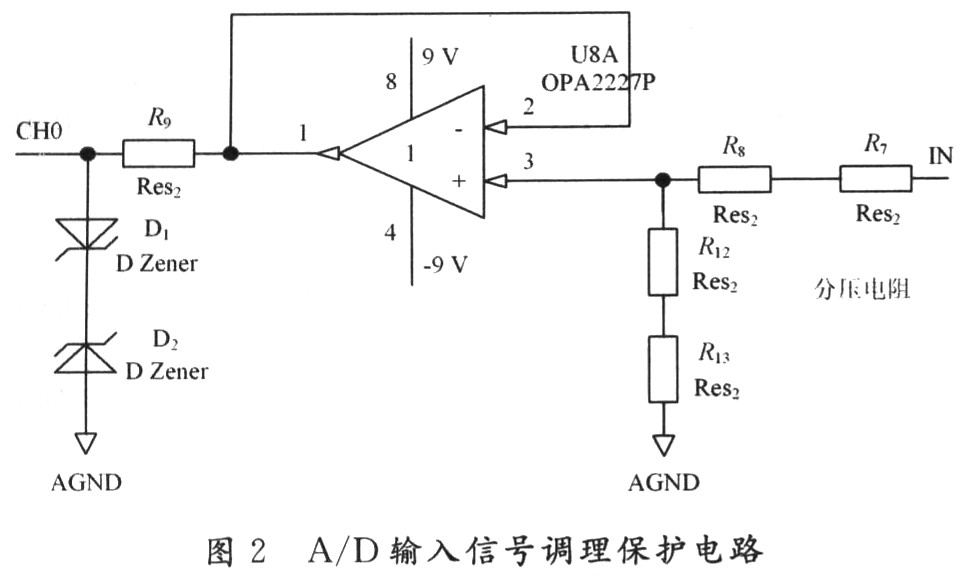
2.2 A / D conversion circuit A / D conversion circuit using MAX1270 chip, MAX1270 is 8-channel, multi-range bipolar input, serial output, successive approximation 12-bit A / D converter, the highest sampling rate is 110 kS /s. The ±5 V, ±1O V, 5 V, 10 V range is programmable from a single +5 V supply. Among them, the bipolar input is very suitable as an AC voltage measurement.
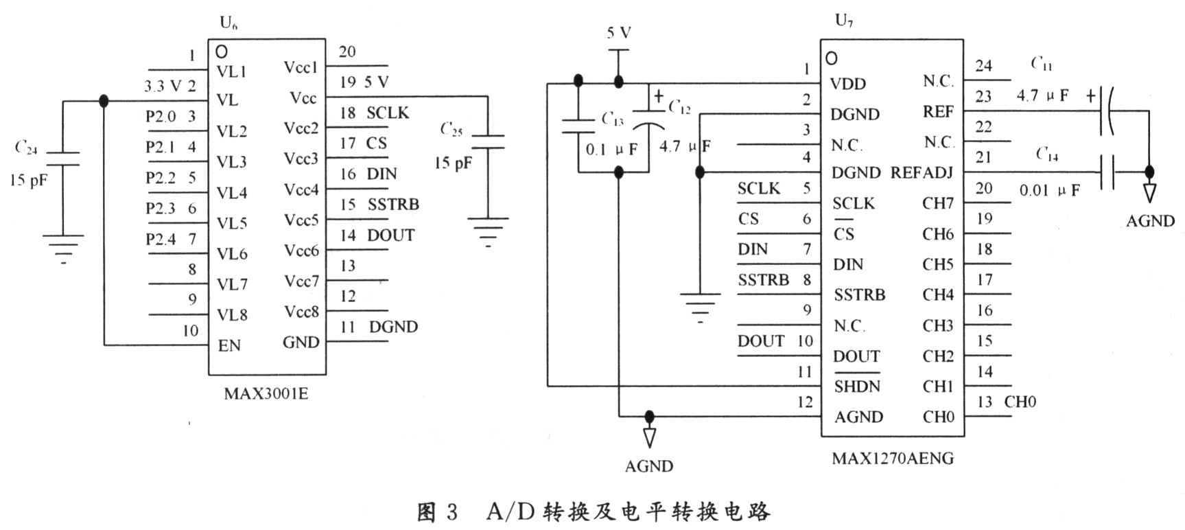
The MAX1270 conversion circuit is shown in Figure 2. The serial interface of the MAX1270 is controlled by the I/O line of the MSP430F449. Since the MAX1270 is powered by a 5 V supply and outputs a high level above 4.5 V, and the MSP430F449 has an I/O port level of 3.3 V, an interface chip must be added to achieve a 5 to 3.3 V Level shifting, here uses the MAX3001 bidirectional level-shifting chip. The A/D conversion circuit is shown in Figure 3.
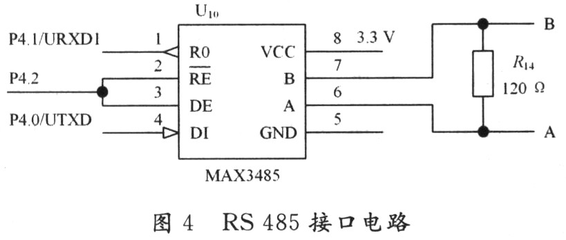
2.3 RS 485 interface circuit This design adopts RS 485 bus, which can effectively transmit the signal to the kilometer through cable or fiber. With the Modbus-RTU protocol, it can be easily connected with the control device complying with Modbus-RTU protocol. The design uses the MAX3485 chip as the RS 485 interface chip, and the circuit is shown in Figure 4.
3 Software Design In the design, the main software modules include A/D conversion, Modbus-RTU protocol and serial port programming. The serial port programming will not be described again, mainly explaining the MAX1270 and Modbus-RTU protocols.
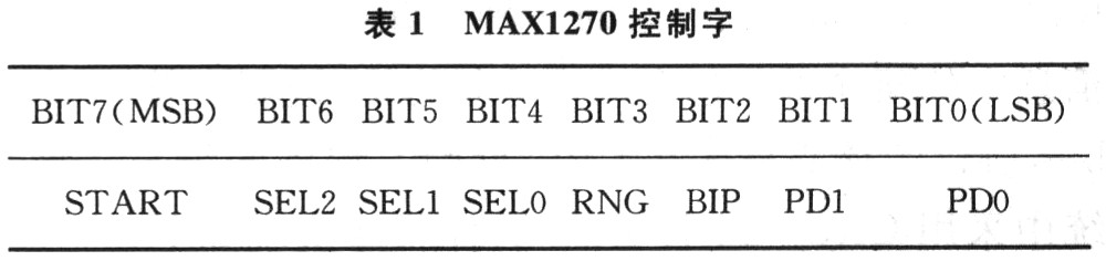
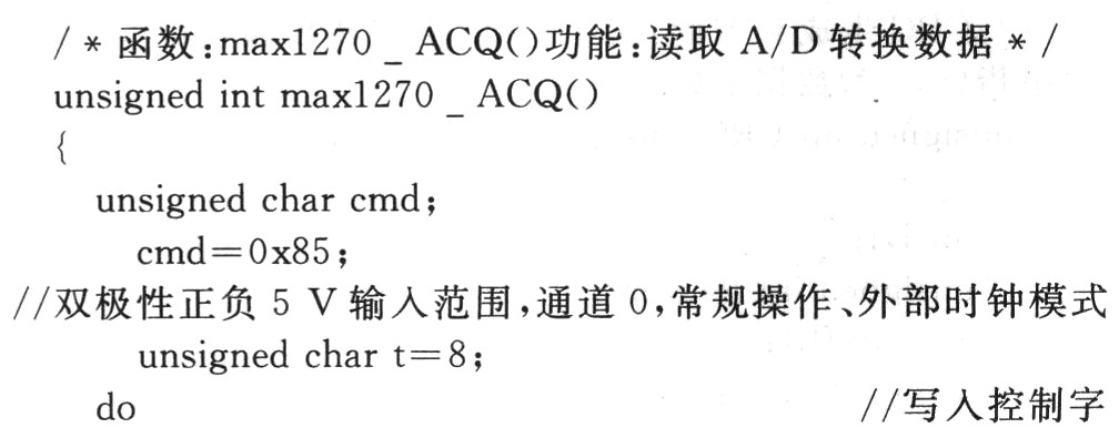
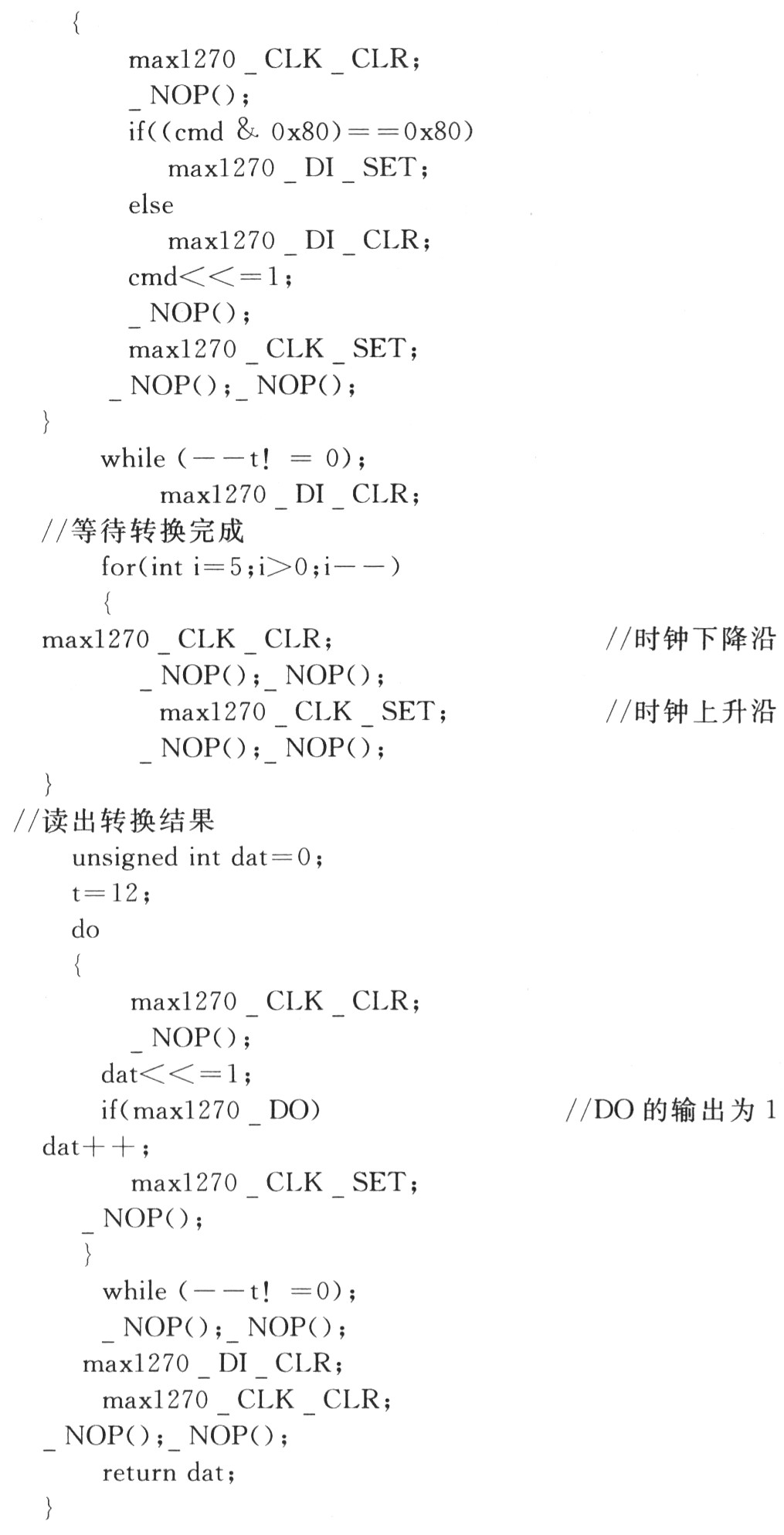
3.1 MAX1270 Programming The MAX1270 control word format is shown in Table 1. The highest START is the start bit and remains "1"; SEL2 ~ SEL0 are the input channel select bits; RNG, BIP are the range and polarity select bits respectively; PD1 and PD0 are power-down and clock mode select bits. Please refer to the MAX1270 data sheet for the specific meaning of each person. In this design, the MAX1270 is set to: 10 V range, bipolar input (ie, 5 V measurement), external clock 25 CLK/s normal operation mode, channel CH0 is used as the input channel, and the format of the control word is 10000101.
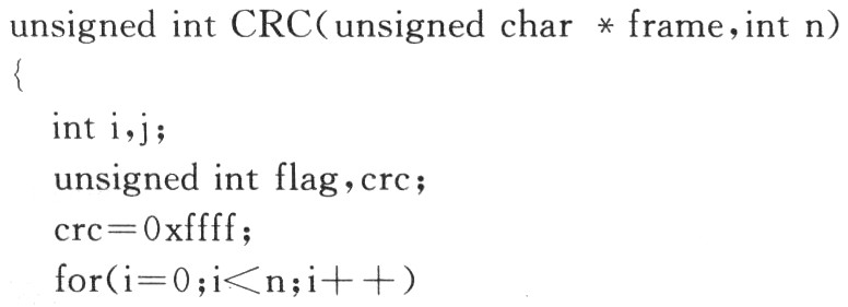
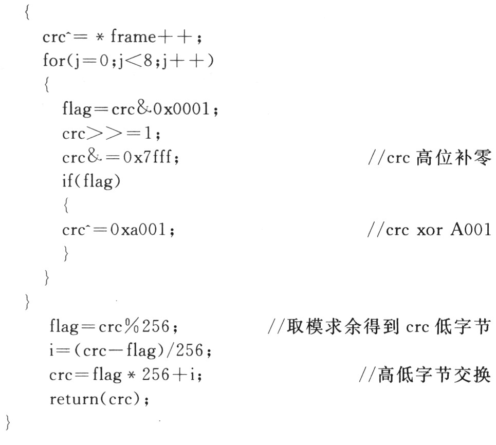
3.2 Modbus-RTU Protocol The Modbus protocol is a general-purpose language applied to electronic controllers. Through this protocol, controllers can communicate with each other and between controllers via a network (such as Ethernet) and other devices. Modbus - RTU is a transmission mode of the Modbus protocol, in which each 8 b in the message contains two 4 b hexadecimal characters. The core program of the Mod-bus protocol is the preparation of the CRC check procedure. The system uses the CRC-16 check method, and the specific program is implemented as follows:
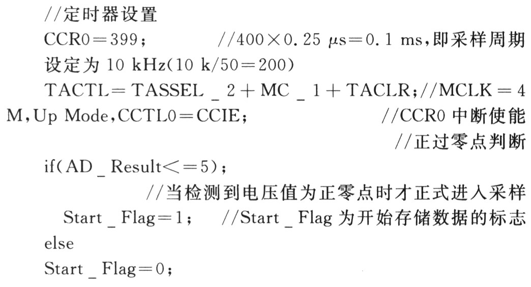
3.3 Other important subroutines The timer interrupt is used to trigger each sampling to ensure the accuracy of the acquisition cycle. At the same time, the zero crossing is used as the beginning of the acquisition data. Both of these points are beneficial to improve system accuracy.
4 Test results By applying standard sine wave, non-standard sine wave and triangle wave test, the peak measurement accuracy of this watch can be higher than level 1, which fully meets the requirements of power supply detection for industrial field devices. This table works well with the industrial control configuration software MCGS and works well. In addition, in addition to measuring the peak value, the table also expands the calculation of the voltage average value and the effective value, and is designed as a smart meter with multiple functions.
5 Conclusion The design uses MSP430F449 MCU and MAX1270 as the core, and writes the Modbus-RTU protocol. At the same time, the RS 485 interface can be used for data remote transmission or connection with devices complying with Modbus_RTU protocol. The table is small in size and low in power consumption. It can be used for battery or battery power supply. It is very suitable for use as a portable device. It can also be carried as a function module. It can also be directly installed in an industrial field device to monitor the peak value and effective value of the grid supply voltage.
UKK Power Distribution Box- 95% contact- Flame retardant:UL94 V0- Nickel-plated copper conductor:copper cable or aluminum cable- The maximum withstand short-circuitcurrent can reach 100KA- Comply with ROHS,CE- Flexible busbars can be directly ibserted into the connection(UKK 500A)- Flexible busbars can be inserted and connectedwith flat connectos(UKK 250A&UKK 400A)
Power Distribution Terminal Box , Brass busbar Distribution Terminal blocks with removable cover A Distribution block is an economical and convenient way of distributing an electrical circuit from a single input source, to several devices in the branch circuit. Thus reducing the total number of wires in your electrical panel and saving you time and money. The exclusive compact and modular design of our distribution blocks.
Distribution Box Metal Box,Distribution Metal Box,Distribution Box Panel ,Electrical Power Distribution Box
Wonke Electric CO.,Ltd. , https://www.wkdq-electric.com