Suggestions for clock tolerance correction in the CAN standard
CAN is an event-triggered communication protocol. It uses identifier (ID) lossless arbitration to schedule the transmission of different messages. Arbitration relies on bit values, so the accuracy of bit value sampling is important. In order to get the same accurate sampling at all nodes, the synchronization of the bit time is the key. In normal transmission, the sampling point variation caused by the clock difference between nodes must be overcome to reduce errors during reading. But whether the bit time can be synchronized depends on the clock deviation. To this end, the CAN standard specifies the calculation method of the clock tolerance. It is now found that the calculation formula specified in the standard is not enough, it will affect the reliability of the application. In particular, the standard 939 commonly used in the automotive industry is based on CAN 2.0B, and the clock tolerance is equivalent to CAN 2. The influence of OB is large, so it is very important to correct this. A complete understanding of the standard is not only directly related to the application, but also has new implications for further improving CAN performance.
1 ISO 1 1898-1: 2003 Provisions on Clock Tolerance
ISO 11898-1: 2003, section 12.4.1.2 specifies the bit time unit as Tq, which is a configurable parameter. There are a total of NTQ (8-25) Tqs in one bit. Tq is obtained by dividing the frequency of the oscillator. It is limited by the resources of the oscillator and the divider of the hardware, and its selection is limited. Each bit is divided into 4 segments: synchronization segment S (Tq), transmission segment Pr (Tq ~ 8Tq), buffer 1 segment P1 (Tq ~ 8Tq) and buffer 2 segments P2 (Tq ~ 8 Tq), they are all configurable Parameters. The sampling of the bit value is at the boundary between P1 and P2. CAN divides synchronization into 2 types: hard synchronization and resynchronization. When the bus is idle, the transition from the hidden bit to the explicit bit of the new frame SOF (R / D transition edge) causes hard synchronization, and immediately resets the status time to the S segment. The R / D transition edge in frame transmission causes resynchronization. When the transition edge falls on the P2 segment after the previous sampling, the P2 is shortened. When the transition edge falls on the S, the length of the local bit P1 is increased. The maximum absolute amount of local time correction does not exceed the value of SJW (Resync Jump Width). SJW is a configuration parameter, between Tq ~ 4 Tq. For more in-depth discussion on CAN bit time and synchronization, please refer to the reference.
In the CAN standard, the term oscillator tolerance is used to represent clock tolerance. In actual implementation, some implementation schemes use an oscillator plus a phase-locked loop to form a clock. At this time, the clock deviation of CAN is composed of 2 parts. In order to be consistent with the standard text, this article does not strictly distinguish between the clock tolerance and the oscillator tolerance. When the relative error of the frequency of the oscillator is expressed as â–³, according to the provisions of 12.11.2.5 of ISO11898-1, there are two constraints.
â‘ During normal transmission, the distance of resynchronization is at most 10 bits due to the rules of CAN filling bits. For correct synchronization, there are:
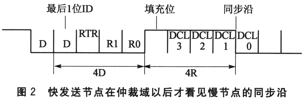
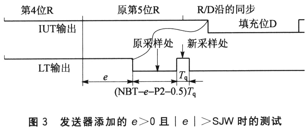
(2 × △ f) × 10 × NBT Among them, NBT is the nominal bit time. ②When there is an error, the node with the error must send an error frame. In order to distinguish whether it is a local error or a global error, it is necessary to investigate whether the 7th bit after issuing the active error flag is still a significant bit. Since there may be 6 significant bits before the error, the 2 sync segments S are separated by 13 bits. The allowable difference is less than the buffer length: (2 × △ f) × (13 × NBT-P2) Choosing the smallest of the two inequalities is the clock tolerance of this application. For example, when Tbit = 1 000 ns, the bus length is 20 m, and the delay of the transceiver is 150 ns, the entire transmission delay is Tprop = 500 ns, take Tq = 125 ns, calculate Pr = 4, P1 = 1, P2 = 2, SJW = 1, NBT = 8. The Δf calculated from the above two equations are 0.006 25 and 0.004 90 respectively, and the smaller one is 0.0004 90, which is close to 0.5%. 2 Problems in transmitter clock synchronization The CAN bus has the feature that the dominant bit has priority over the hidden bit, that is, when multiple nodes on the bus send at the same time, as long as one node sends the dominant bit, the final result on the bus is the dominant bit. Therefore, when two nodes with a certain distance are sent at the same time, because of the time required for transmission, the R / D transition edge of another node cannot be seen at one node (as shown in Figure 1, e is the synchronized phase Poor), because the level of the bus has already been set to the dominant bit by this node. In this case, nodes A and B cannot establish synchronization even if the clocks are different. Let A be faster than B. Only when the synchronization segment S of node A is more advanced than the synchronization segment S of node B, and its lead is greater than the transmission time, can node B see the R / D transition edge of A, and B Synchronization will begin. Now analyze the synchronization problem of the two transmitters in the arbitration area. Suppose they see that the bus is idle and start to send at the same time, their ID is only the last one is different. There are literatures describing the synchronization process of the sending node, assuming that when the bus is idle, there is a transmitter that leads the other transmitters and exceeds Pr / 2 segment transmission. Due to the random nature of the incident, this is only a special case. For timing messages, they are triggered by the local node's clock. But the local clocks are not synchronized, and there is a frequency difference between them, so the timing message specifies that the phase difference of the time that should be sent out will change periodically. The case where one transmitter leads all other transmitters is only a special case. Under the assumptions of this article, since the R / D transition edges appearing before each ID are not seen by the other party, there is no synchronization relationship between them. To the last bit, assuming that the node with a slow clock has an explicit bit and the node with a fast clock has a hidden bit, and assuming that the first bit of the ID is a hidden bit, then the R / D transition edge of the slow node may be seen by the fast node . However, it will have a large phase difference, and may have exceeded the re-synchronization jump width SJW, so that the fast node cannot be synchronized correctly, which will cause the sampling to produce a bit value where the level sent by the slow node is not yet stable. Read wrong. In the last bit of the 29-bit ID of CAN 2.0B, which is the 31st bit of the arbitration field, there may be 7 padding bits, that is, 37 bits have not been synchronized. In order to sample correctly, the difference between the sync segment of the fast and slow sending nodes when not synchronized should be less than the re-synchronization jump width SJW: (2 × △ f) × 37 × NBT≤SJW (3) Taking the data of the previous example, NBT = 8, SJW = 1, we get △ f≤0.001 68, which is much reduced. Since receivers close to the fast node can see the R / D transition edge of the fast node, they have been synchronized according to the fast node. Finally, they must be synchronized according to the slow nodes that have not been synchronized, and they will also encounter synchronization problems when the phase difference is large. If the last 2 digits of the ID are already significant, then the fast node will not see the transition edge of the slow node, because there is no R / D transition edge available for synchronization at this time. The receiver synchronized with it will be completely unable to synchronize with the slow node. They will be sampled according to their original phase and bit time. In the worst case, it is necessary to go through 7 bits to see the next R / D transition edge of the slow node, as shown in Figure 2. The transmitter that fails to see the transition edge in the arbitration domain has now become the receiver. However, if the subsequent transition edge can ensure correct synchronization, then the offset of the sampling point in the arbitration domain is smaller. , Should be able to ensure the correct sampling, that is, the correct arbitration. At this time, the maximum number of unsynchronized in the arbitration domain is 40 (including the possible 8 bits of padding), and then the most recent transition edge is after 6 bits, so in order to be able to sample correctly, there should be: (2 × △ f) × 46 × NBT≤SJW (4) Still taking the data in the example in the first part, NBT = 8, SJW = 1, we can get △ f≤0.001 35, which is smaller. If NBT = 25 and SJW = 1 in a system, △ f≤0.0043 can be obtained. This is a fairly small value. According to the above analysis, the worst case is (4). For CAN2.0 A, the corresponding worst case can be derived as: (2 × △ f) × 21 × NBT≤SJW (5) If the transmission time is relatively short and the slow node has synchronized with the fast node after delaying Pr / 2, the fast node will see the synchronization edge from the slow node with e = Pr at the bit that the slow node finally wins. To ensure synchronization, at least: Pr≤SJW (6) If equation (6) is satisfied, synchronization can occur. For example, in a system with a small share of transmission delay time, the original ISO11898-1 formula is used. In use, when reading the ACK bit, the worst sync edges will be 11 bits apart (CRC delimiter is not in the padding bit rule), and equation (1) should also be modified. If formula (6) is not satisfied, such as high-speed systems, formula (4) or (5) should be considered. ISO11898-1 should add the above content. Generally speaking, equations (4) and (5) are stricter than equations (1) and (2). If they need to be simplified, they are sufficient. For example, for CAN2.0A, using the data of the previous example, NBT = 8, SJW = 1, △ f≤0.002 97 can be obtained from equation (5), which is also better than the original 0.0004 90. 3 Provisions to be added to ISO 16845: 2004 The ISO16845 conformance test clauses on transmitter time synchronization related functions have a total of 9 items (8.7.1-1.8.7.9), of which there are only 2 items used for resynchronization with phase difference: 8.7.4 Synchronization when e <0 and | e | ≤SJW; 8.7.5, when P <0 and e> SJW. From the analysis in Part 2, we can see that the last bit that the transmitter exits in arbitration needs to be synchronized, at this time it is still the state of the transmitter. Only after synchronization, can we sample correctly, decide whether to exit and ensure that the winning transmitter can be tracked correctly after exiting. Therefore, you need to add e> O, and | e | ≤ SJW, and e> 0, and | e |> SJW test clause. These terms can refer to the corresponding terms of the receiver (7.7.3 and 7.7.4). The low-level test equipment LT in ISO 16845 is a dedicated device, which is connected to the Tx and Rx of the CAN under test (called the tested IUT). The LT generates the necessary input conditions to Rx, and then measures the IUT response from Tx whether it is passed. LT should not affect the IUT during non-test input. Take the test when e> O and | e |> SJW as an example, arrange the IUT to send 1 frame with padding bits as the explicit bits in the ID field. When the fifth hidden bit is sent, LT delays e to change Rx to a significant bit, and then builds a hidden bit value for Rx at the new sample point after the delay (the original P1 + SJW). At this time, the IUT output Tx A bit will be provided after the R / D transition edge provided by LT according to the synchronization rules, as shown in Figure 3. The above test design is based on the following principle: if the IUT is operating normally, it will synchronize to the R / D transition edge provided by LT and acquire the hidden bit provided by LT, at this time it sends out its next padding bit, the R / of the padding bit. The D transition edge has been moved by the previous synchronization of the IUT. If the synchronization is not normal, or the amount of the jump is incorrect, the IUT will pick up the display bit, it will quit the arbitration and will not send again. The range of tested P is (SJW + 1) ~ (NBT-P2-1). This design is different from the standard 7.7.4. The author believes that the method of 7.7.4 can not achieve the purpose, and a detailed discussion of this issue is beyond the scope of this article and will not be repeated here. It should be pointed out that the transmitter in 8.7.2, which is transmitting the significant bit, will not synchronize the R / D transition edge with e> 0. This requirement is different from the synchronization problem described in this article when e> 0. This article is about the transmitter's hidden bit, it sees the R / D transition edge of other transmitters; and 8.7.2 only describes the characteristics of the CAN chip's Tx and Rx separately for output and input testing. Actual The application is inseparable and will not encounter this situation. 4 Summary The general technical data of CAN all mentioned that the reliability at high speed is worse than that at low speed, and low speed can be used in applications where low speed is available. From the analysis of the above-mentioned bit synchronization clock tolerance, it can be seen that the clock tolerance is small at high speed, so if there is a problem with the clock, it will affect synchronization and sampling. The CAN standard ISO11898-1: 2003 only considers the requirements of some occasions, and does not consider the situation where the transmitter arbitration phase is not synchronized, so the tolerance results given are wide, and the designer may choose inappropriate oscillation accordingly. Source, resulting in insufficient reliability of the electronic controller (ECU). For example, there are already some correctable RC or CMOS oscillators with accuracy close to 0.3% to 2%. They are low in price and close to the tolerance of the original CAN standard design, which may be inappropriately selected. Therefore, it is necessary to supplement the standards. With the expansion of CAN applications, efforts to increase CAN operating frequency are continuing. On the one hand, some applications can shorten the transmission distance to shorten the transmission time, such as robots, weapons, etc .; on the other hand, CAN has a high cost performance, which is attractive for such applications. When the transmission time is close to the critical situation, more attention should be paid to The problem of clock tolerance. Considering the possibility of solving the problem from another angle: the synchronization between the transmitter and receiver in the arbitration domain and the first synchronization edge after arbitration is set to hard synchronization. This method can improve the sampling after synchronization, but does not improve the sampling before synchronization. They still require a higher precision clock to ensure that the sampling point is within the buffer segment P1, P2. Moreover, too much hard synchronization increases the chance of unnecessary synchronization of interference, which is not a good thing. Therefore, this solution is worthless. It can be seen from the analysis that when the resynchronization jump width SJW can be selected to be larger, the allowable clock deviation is larger. Unrestricted SJW is equivalent to performing hard synchronization at any time. SJWs smaller than P1 and P2 make the variation of sampling points smaller. When a false R / D transition edge occurs on the bus due to interference, it will cause erroneous resynchronization. A small SJW helps reduce the probability of read errors. Therefore, taking into account the requirements of reducing the error rate and lowering the tolerance of the clock, the key is to design a cost-effective method of filtering interference. Capacitor Leakage Test Power Supplies The ADP series capacitor leakage test power supply is specially designed and customized for capacitor manufacturers` product quality control process or users of capacitors for capacitor ripple current durability life test.
Capacitor Leakage Current Power Supplies, Leakage Current Ripple Power Supplies, AC and DC Power Supplies, Capacitor Test Power Supplies, Ripple Current Test Power Supplies Yangzhou IdealTek Electronics Co., Ltd. , https://www.idealtekpower.com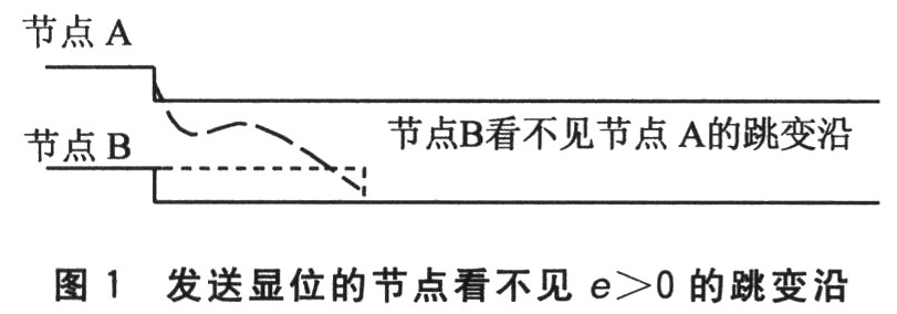

Capacitor leakage current test power supply is aimed at the diversity of output voltage and frequency required for different capacitance tests with the DC output voltage up to 3000Vdc, the AC voltage output up to 200Vac, the AC current up to 500A, and the output frequency can be selected according to customer requirements from 50Hz to 100KHz.
Equipped with special high-frequency and high-temperature fixtures and connecting wires for capacitor leakage current testing, the capacitor leakage current test power supply can imitate the actual working conditions of capacitors to determine the service life of a group of capacitors under test, providing the accurate parameters of capacitors required by the manufacturer for the capacitors R&D and quality inspection test, the power supply is now aiding the test of high-frequency and high-current passive devices such as high-frequency capacitors, film capacitors, electrolytic capacitors, ballast capacitors, and ballast inductors.