Abstract: This paper introduces a realization method of solar-powered high-brightness white LED flash circuit, which has high application value. The realization scheme of the solar battery panel charging phase and the design of the flash control circuit are given, and the service life of the high-brightness white LED is analyzed. The solution to extend the service life is also presented. The extensive use of integrated ICs enables the system to achieve static low power consumption and stable use.
Key words: solar energy; white LED; flash circuit; low power consumption
1 Introduction
The flash device described in this article is an auxiliary lighting device when the camera captures the vehicle overspeed on the highway. According to the requirements of field work, lighting equipment needs sufficient energy source and sufficient service life. This circuit adopts the method of solar battery power supply, so the equipment is required to have static low power consumption characteristics. Compared with other lighting equipment, white LEDs have the advantages of high brightness, low power consumption and long life. This paper will introduce a design scheme of a solar-powered high-brightness white LED flash circuit, explain the design of the power supply and the implementation of the static low power consumption of the circuit, and discuss the issues that should be paid attention to during the design process.
2 system components
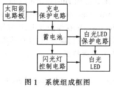
Figure 1 is a block diagram of the composition of the system. The following is an analysis of the charging protection circuit portion, the flash control circuit portion, and the white LED protection circuit portion of FIG.
2.1 Solar charging protection circuit
2.1.1 Solar panels
Solar panels not only provide electricity during the day, but also provide electricity during the night. Like the transistor, the solar panel consists of a semiconductor, the main material is silicon, and there are some other alloys.
The surface of a solar panel consists of two distinct parts. When exposed to light, it is possible to convert light energy into electrical energy, causing current to flow from one side to the other.
As long as the solar panel is exposed to sunlight or light, it can generally emit 1/10 of the received light energy. In order to minimize the light reflection of the solar panel, the light energy is converted into electric energy, and a film for preventing light reflection is generally deposited thereon, so that the surface of the solar panel is purple.
The solar power supply part is mainly composed of a solar panel (photovoltaic module), a charging circuit and a battery. Photovoltaic modules absorb light during the day and convert solar energy into electrical energy for storage in solar cells. Generally, on a sunny day, under ideal light intensity, it takes only 4 hours to fully charge. The system adopts 15V solar panel, and the actual measured voltage of the battery board is 17V~20V, and the charging current is 200mA~800mA.
2.1.2 Battery pack capacity design
The energy storage device of the solar battery power system is mainly a battery. The battery that is matched with the square array of solar cells usually works in a floating state, and its voltage varies with the amount of power generated by the square array and the amount of power used by the load. Its capacity is much larger than the amount of power required by the load. The energy supplied by the battery is also affected by the ambient temperature. In order to match the solar cell, the battery is required to have a long working life and simple maintenance.
(1) Selection of battery
There are many types of batteries that can be used with solar cells. Currently, there are three kinds of lead-acid maintenance-free batteries, ordinary lead-acid batteries and alkaline nickel-cadmium batteries. At present, the domestic use of lead-acid maintenance-free batteries is very suitable for reliable solar power systems, especially unattended workstations, because of its inherent “free†maintenance characteristics and less environmental pollution. Ordinary lead-acid batteries are mainly suitable for maintenance or low-end applications because they require frequent maintenance and environmental pollution. Alkaline nickel-cadmium batteries have good low temperature, overcharge and overdischarge performance, but because of their high price, they are only suitable for more special occasions.
(2) Calculation of battery capacity
The capacity of the battery is important to ensure continuous power supply. In a year, the power generation of the square array is very different every month. In the month when the power generation of the square array cannot meet the needs of electricity consumption, it depends on the energy of the battery; in the month that exceeds the electricity demand, the surplus electric energy is stored by the battery. Therefore, the shortage and excess value of the square array power generation is one of the basis for determining the battery capacity. Similarly, the load power during continuous rainy days must also be taken from the battery. Therefore, the power consumption during the period is also one of the factors determining the battery capacity.
Therefore, the battery capacity Bc is calculated as:

Where: A is the safety factor, which is between 1.1 and 1.4; QL is the average daily power consumption of the load, which is the working current multiplied by the daily working hours; NL is the longest continuous rainy day; To is the temperature correction coefficient, generally Take l above 0 °C, take 1.1 from -10%, and take 1.2 below -10 °C; Cc is the discharge depth of the battery, generally 0.75 for lead-acid batteries and 0.85 for alkaline nickel-cadmium batteries. According to the requirements of this system, through calculation, 12V8Ah ordinary lead-acid battery is selected.
2.1.3 Charging protection circuit
The solar charging protection circuit consists of two parts: overcharge and overdischarge protection.
Overcharge protection: When the solar panel charges the battery so that the battery output voltage exceeds 14.5V, the overcharge path control relay stops the solar panel from charging. When the battery output voltage drops back to 14V, the solar panel recharges the battery.
Over-discharge protection: When the battery output voltage is lower than 10.5V, the battery stops supplying power to the external circuit. When the battery voltage exceeds 10.5V, re-power the external circuit.
The charge protection circuit consists of two operational amplifiers, as shown in Figure 2. In Fig. 2, Vi1 and Vi2 are respectively the output voltage of the battery, and Vref is the comparison reference voltage of the operational amplifier, and the specific value is set by the user according to different requirements. In the actual design process, attention should be paid to the selection of the feedback resistor in Figure 2. The larger the feedback resistance, the smaller the input Vi return difference corresponding to the control output.
2.2 flash control circuit
The control circuit needs to be designed differently according to different requirements. The control circuit with complex flash function can be controlled by MCU microcontroller, which is convenient, simple and stable. Since the design of the system only requires flash timing flashing and a single function, it is implemented by a simple pure hardware circuit. The circuit composition is shown in Figure 3.
2.2.1 Pulse generation circuit
This circuit uses a 4047 pulse generator. The 4047 has a simple external structure, stable performance, and very low static power consumption (static measured value is 0.5mA). The output signal of 4047 is used as the trigger pulse of the frequency dividing circuit, and the frequency of the output signal is controlled by an external capacitor and a resistor.
2.2.2 Frequency dividing circuit
This circuit is implemented using a 14-bit binary calculator 4020. The pulse signal outputted by 4047 is used as the pulse input signal of 4020, so that the 4020 performs binary counting to achieve the frequency dividing purpose. Its feature is a 14-bit crossover output, which can be selected according to different design requirements, and the static power consumption is 1mA.
2.2.3 Monostable Trigger Circuit
The monostable trigger circuit can be composed of simple flip-flops, but such a circuit design is not stable and consumes a lot of power. In order to avoid the above shortcomings, the system uses integrated chip 4538. 4538 is an edge-triggered circuit, which can be set to rise edge trigger and falling edge trigger according to different input signals. In this system, the 4020 output signal is used as the input pulse of 4538 for monostable trigger. The output pulse width is controlled by external capacitor and resistor. The output pulse period is determined by the frequency of the input pulse provided by 4020. Finally, the signal output from the 4538 output is used as the switch control signal for the LED lamp.
The main feature of this part of the design is the full use of medium-scale integrated devices to achieve high stability and low static power consumption.
2.3 white LED protection circuit
2.3.1 Introduction to White LED
White LED is the most promising LED emerging product, and its development potential in the lighting market is worth looking forward to. Compared with incandescent tungsten bulbs and fluorescent lamps, LEDs have small size (multiple combinations, multiple combinations), low heat generation (no heat radiation), low power consumption (low voltage, low current start), and long life (1) More than 10,000 hours), fast response (can be operated at high frequency), environmental protection (shockproof, impact resistant, not easy to break, waste can be recycled, no pollution), flat packaging, easy to develop into light and short products, no incandescent bulbs The shortcomings of high-consumption, fragile and fluorescent lamp waste containing mercury pollution are a potential commodity that is favored by the industry in the next 10 years to replace traditional lighting fixtures.
2.3.2 White LED performance analysis
(1) White LED color, wavelength analysis LEDs that actually emit white light do not exist. Such devices are very difficult to manufacture because LEDs are characterized by emitting only one wavelength. White does not appear on the spectrum of color; an alternative method is to synthesize white light using different wavelengths.
A small trick was used in the design of white LEDs. The blue-emitting InGaN binder is covered with a conversion material that emits yellow light when excited by blue light. A mixture of blue and yellow light is thus obtained, which is white to the naked eye. Figure 4 is a schematic diagram of the wavelength and forward current of the LED. As can be seen from Figure 4, the emission wavelength (solid line) of the white LED includes the peaks of the blue and yellow regions, but is white to the naked eye. The relative light sensitivity (dashed line) of the naked eye is shown in Figure 4.
However, LEDs using InGaN technology are not as easy to control as standard green, red and yellow. The display wavelength (color) of the InGaN LED changes with the forward current (as shown in Figure 5). For example, the color variations exhibited by white LEDs result from different concentrations of the conversion material, and the blue light-emitting InGaN material produces a wavelength change as the forward voltage changes.
When the forward current is as high as 10 mA, the forward voltage changes greatly. The range of variation is approximately 800mV (some models will vary more diodes). A change in the operating voltage caused by the discharge of the battery changes the color because the change in the operating voltage changes the forward current. At 10mA forward current, the forward voltage is approximately 3.4V (this value will vary from vendor to vendor, ranging from 3.1V to 4.0V). Similarly, the current-voltage characteristics between different LEDs are also quite different. It is difficult to drive the LED directly with the battery, because the vast majority of the battery will have a lower voltage than the minimum forward voltage required by the LED.
(2) Analysis of volt-ampere curve and temperature current change of white LED
Figures 6 and 7 show the volt-ampere curve and temperature-current curve of the LED, respectively. It can be known from the principle of LED illumination that the change in brightness of a white LED is mainly determined by its current.
From the above white LED analysis can be seen:
(1) The current of the white LED will affect its wavelength change;
(2) When the LED operates in the region of 10mA to 30mA, the voltage across the LED will change slightly, and the current will change greatly;
(3) The current withstand range of the LED becomes smaller as the temperature increases.
In order to make white LEDs work stably for a long time, the following measures are taken:
(1) Pull apart the distance between the two LEDs to achieve the purpose of heat dissipation;
(2) Using constant current power supply, the wavelength and brightness of the white LED are in a constant state.
From the above analysis, it can be concluded that in order to maintain the LED in a fixed brightness and color luminescence, and to extend its working life, the forward current must be maintained at a stable value, so constant current measures are taken to ensure stable operation of the LED.
2.3.3 Constant current protection circuit
The system uses a high-current CMOS tube as an electronic switch, and uses a constant current circuit to supply constant current to the LED array, so that the LED lamp can work stably for a long time. The following describes the implementation of constant current.
Figure 8 is the basic diagram of the most basic constant current circuit. In the figure, RL is the load resistance (actually the LED array), Ro is the sampling resistor, and Eg is the reference voltage. The output current Io=Eg/Ro indicates the output of the steady current power supply. The current is determined by the reference voltage Eg and the sampling resistor Ro. Once Eg and Ro are determined, the output current of the steady current power supply is not affected by the output power supply voltage and load. It can be seen that in order to obtain a stable output current, it is necessary to provide a high-precision reference voltage and sampling resistor.
According to the above basic principle diagram, the system uses a CMOS field effect transistor and an operational amplifier to form a basic constant current circuit. In this system, the reference voltage Eg is supplied by the output pulse of the 4538 in the control circuit through a voltage stabilizing circuit (using a TL431 regulator). Whenever a positive pulse is output from 4538, it will trigger the operation of the operational amplifier in the constant current circuit to illuminate the LED to achieve the effect of constant current flash.
3 Conclusion
After testing, the static power consumption of the system circuit is 5mA~7mA, with low static power consumption and high stability. Different users can modify some of them to meet the design requirements according to different design requirements.
(Editor: Wen Jing)
Stainless Steel Hexagonal Bar,420 Stainless Steel Hexagonal Bar,Stainless Steel Bar Metal Rod,Stainless Steel Bar Top
ShenZhen Haofa Metal Precision Parts Technology Co., Ltd. , http://www.haofametals.com