This article refers to the address: http://
1 IntroductionSince the radio adopts a fully transparent transmission mode, as long as the frequency band is the same, the speech signal transmitted in the same frequency band can be received, so that it is impossible to accurately distinguish whether the signal is useful. Stations with voice encryption can avoid this situation, but in some areas or places that require high confidentiality, such as the military field, once the interceptor breaks our encrypted signal, it sends a misleading voice signal. It cannot be discerned and may cause some loss. Therefore, here is a system based on the C8051F microcontroller that recognizes the identity of the station in DTMF encoding. The system is simple to use, and it can realize the identification of the radio identity by simply connecting to the extension port of the radio station without changing the original characteristics of the radio station. Even if the other party cracks the voice signal, the address can be used to distinguish the identity of the station. The system has certain application prospects in the field with high confidentiality requirements.
2 system composition and working principle
Figure 1 is a block diagram of a system for identifying a station identity. The MCU selects C8051F020, the DTMF unit selects MT8880 dual-tone multi-frequency device, the voice storage play module adopts ISD4004, in addition, there are display unit, storage unit and keyboard.
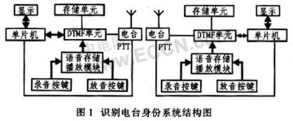
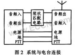
Radio stations generally reserve expansion interfaces: audio input, audio output, PTT transmission control, power supply, and ground. The system is connected to the radio through these interfaces, as shown in Figure 2.
System working principle: As a transmitter, the radio station presses the FTT key, PTT changes from high level to low level, and sends the signal to the MCU. The interrupt program of the MCU sends the address code of the machine to the MT8880 through the data interface. After being modulated by MT8880, it is sent to the audio input interface of the radio station and sent along with the voice signal. As a receiver, it needs to be divided into various situations, as shown in Figure 3.
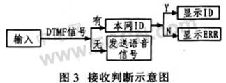
After receiving the voice signal, it is determined whether there is a DTMF signal input. If there is, MT8880 decodes, and the decoded data is transmitted to C8051F020, C805117020 to determine whether the address is a predetermined station address code. If yes, the address code is displayed on the LCD, otherwise it displays ERROR; if there is no DTMF signal and only the voice signal, it means that the signal is not the signal in the network, the operator replies to the pre-recorded voice signal through the playback button to confuse the other party. .
3 system hardware design
The whole system can be divided into two parts: DTMF encoding/decoding and voice storage playback. And controlled by the main control unit. Since the system is powered by the battery of the radio, low power devices are used. The main control unit here uses C8051F020. It is a fully integrated mixed-signal system-on-chip (SoC) with an 8051-compatible high-speed CIP-51 core that is fully compatible with the MCS-51 instruction set. The C8051F020 has a clock frequency of 25 MHz and contains 64 KB of on-chip Flash program memory, 4 352 B of RAM, 8 I/O ports, and 64 I/O lines.
3.1 DTMF encoding / decoding
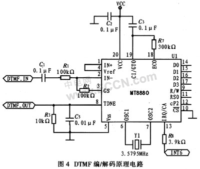
The DTMF encoder/decoder uses MT8880. The MT8880C is a single-chip DTMF signal transceiver with a call processing filter. The device features low-power, high-stability ISO-CMOS technology, a high-performance receiver with a variable gain internal amplifier, a transmitter with a pulse counter, and an accessible MT8880 internal The standard microprocessor interface for registers. Its internal register includes a status register, two data registers and two control registers. The circuit is shown in Figure 4.
The system uses a single-ended input mode, IN- is the op amp input, and R1 and R2 regulate the input signal gain. TDNE is an audio output for transmitting DTMF signals. OSCl is the clock/oscillator input, OSC2 is the clock output, and MT8880 is the 3.579 5 MHz operating clock. IRQ/CA is the interrupt request signal and the open-drain output. When there is DTMF signal input, IRQ/CA issues two parts to C8051F020. And controlled by the main control unit. Since the system is powered by the battery of the radio, low power devices are used. The main control unit here uses C8051F020. It is a fully integrated mixed-signal system-on-chip (SoC) with an 8051-compatible high-speed CIP-51 core that is fully compatible with the MCS-51 instruction set. The C8051F020 has a clock frequency of 25 MHz and contains 64 KB of on-chip Flash program memory, 4 352 B of RAM, 8 I/O ports, and 64 I/O lines.
3.1 DTMF encoding / decoding
The DTMF encoder/decoder uses MT8880. The MT8880C is a single-chip DTMF signal transceiver with a call processing filter. The device features low-power, high-stability ISO-CMOS technology, a high-performance receiver with a variable gain internal amplifier, a transmitter with a pulse counter, and an accessible MT8880 internal The standard microprocessor interface for registers. Its internal register includes a status register, two data registers and two control registers. The circuit is shown in Figure 4.
The system uses a single-ended input mode, IN- is the op amp input, and R1 and R2 regulate the input signal gain. TDNE is an audio output for transmitting DTMF signals. OSCl is the clock/oscillator input, OSC2 is the clock output, and MT8880 is the 3.579 5 MHz operating clock. IRQ/CA is the interrupt request signal and the open-drain output. When there is DTMF signal input, IRQ/CA issues an interrupt request to C8051F020. D0~D3 are microcomputer data bus, compatible with TTL, output measured DTMF signal and input DTMF signal, and connected with I/O interface of C8051F020. The 12-pin CP2 terminal is the system clock input. It cooperates with the R/W of the read/write control terminal to complete the read and write operations of the MT8880. The RS0 pin is the register selection and the TTL level is compatible. The address code can be composed of 0 to 9 and A to D. Due to the particularity of the application field of the system, the address code is encrypted. When the terminal acts as a transmitter, the DTMF encoding/decoding portion encrypts the address code of the terminal by a certain algorithm, and then modulates it into a DTMF signal, and then sends it to the station to facilitate identification by other stations in the network. When the terminal acts as a receiver, the DTMF encoding/decoding portion demodulates the received DTMF signal into a digital code, and then obtains an address code via a decryption algorithm. Considering that the impedance of the system may not match the impedance of the radio audio I/O interface, an audio transformer should be added between the two.
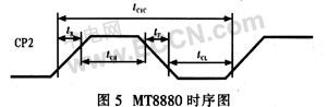
Because the standard PC interface provided by MT8880 is compatible with the 6800 series, if you use other MCU control. The timing of its work must be simulated in hardware or software. The author found in the process of using MT8880, the key is to provide interface clock signal CP2 for MT8880. The typical value of the clock cycle tCYC is 250 ns. In fact, tCYC takes values ​​between 0.167 and 10 s (6 MHz to 100 kHz), and MT8880 can still work normally. Therefore, the value range of tCYC is wide, as shown in Figure 5. Shown. Therefore, the generation of CP2 is more flexible.
In this system, the pin P1.0 of C8051F020 is connected to the pin CP of MT8880 to simulate the working timing required by MT8880.
3.2 Voice storage playback
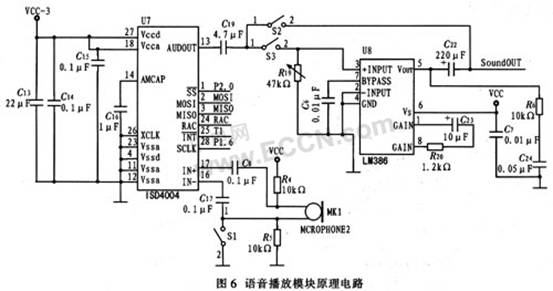
The voice storage player module uses ISD4004 from ISD. The voice device adopts the patented technology of multi-level direct analog memory (Chip Corder), the sound does not need to be A/D converted and compressed, and each sampled value is directly stored in the on-chip flash memory, thereby avoiding the quantization and compression of the general solid-state recording circuit. The resulting quantization noise and metallic sound. Figure 6 shows the principle circuit of voice playback. The voice input is directly connected to the ISD4004 pin IN+, IN- through the microphone (MIC) differential drive input. The voice output is amplified by the LM386 and connected to the voice output of the station. The system uses a keyed segment recording and playback mode. 10 different voices can be recorded through the recording button. Each recording corresponds to a button on the keyboard. According to the received voice signal, different voices can be played through 10 buttons, which is convenient and flexible to use.
4 system software design
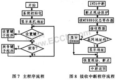
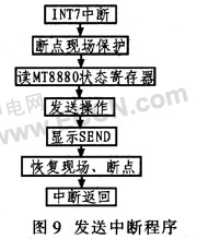
The system program is written in assembly language, and all DTMF's receive/transmit work is done by the interrupt service routine. The main program is only responsible for initialization procedures and keyboard scanning. Figure 7 shows the main program flow. Figure 8 shows the flow of the receive interrupt handler. Figure 9 shows the flow of the transmission interrupt handler.
5 Conclusion
In the development of a certain force project, the above system was successfully used to realize the function of radio identification and automatic voice playback. The actual use proves that the interface of the system is simple and reliable, and satisfactory results are obtained.
12v trolling motor battery,solar powered golf cart,valve regulated lead acid battery,lithium marine batteries ,12v deep cycle marine battery,valve regulated lead acid vrla batteries
EMoreShare International Trade (Suzhou) Co., Ltd , https://www.emoreshare.com