RF engineers who are frequently exposed to cable, terrestrial, or satellite TV applications often need to perform S-parameter tests on these application circuits. Experienced engineers will verify whether the TV tuner produces their expected return loss during the first measurement. If they are consistent, the problem is simplified to: How to measure the S-parameter of the 75W device under test with a 50W vector network analyzer. If the funds are sufficient, the solution is to purchase an experimental instrument (with a 75W source and load impedance test port) dedicated to testing 75W circuits. Otherwise, the minimum loss pad is used to convert the input and output impedance from 50W to 75W. This method is simple and easy, and can obtain reasonable measurement results.
When IC manufacturers need to determine the input return loss of a low-noise amplifier for cable TV, all measurements must be based on 75W. In other words, if the input return loss | S11 | = -30dB (the reflected power is one thousandth of the total power, which is basically an ideal match), when driven by a 75W source impedance, ideally, the device under test basically Transfer all power to the low noise amplifier.
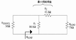
Figure 1 The minimum loss pad used to match the 75W device under test and the 50W test port. Low frequency insertion loss is 5.72dB. The upper limit of the flatness of the frequency response function is determined by the quality of the network configuration.
When driven by a 50W signal source, such as a typical vector network analyzer, signal generator, and noise figure table, the same tuner input will no longer provide good return loss characteristics. Directly connecting the input of this perfectly matched TV tuner to a 50W vector network analyzer will produce an input return loss of -14dB, ie the reflected power will be 1/25 of the total power. Therefore, when using the same 50W vector network analyzer to verify whether the TV tuner input is normal, certain measures need to be taken. In this case, the corresponding matching circuit is necessary. The matching circuit must have a flat frequency response curve and the lowest possible insertion loss. The widely accepted solution in the industry is to use the minimum loss pad (abbreviated as MLP). Figure 1 is the simplest pure resistance network. The most obvious feature of this network is the ability to convert input and output impedance from 75W to 50W, or from 50W to 75W. This can eliminate reflections, make the response characteristics flat, and the network loss can be very easily calibrated from the test instrument to the device under test. Many test equipment manufacturers can provide such minimum loss pads, and the network is easy to set up.
See the appendix for the mathematical derivation formula for the conversion from ZLOAD to ZLOAD '. The resulting ZLOAD 'expression illustrates the cascade impedance of the equivalent MLP and DUT of the test port (RSOURCE). Transform the formula and use ZLOAD 'to solve ZLOAD. Taking this method can reflect the influence of MLP, and can determine the true ZLOAD value from the test data. The result is:
The corresponding verification process is also necessary. For example, an impedance measurement is performed on a 75W resistor through MLP, and it is assumed that the network vector analyzer determines RLOAD '= 50W (return loss is infinite). Assuming RLOAD '= 50W, we get R1 = 43.3W and R2 = 86.6W, and ZLOAD = 75W as expected.
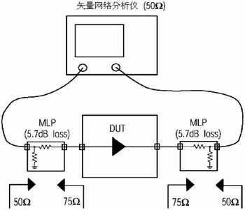
Figure 2 Using a 50W VNA to test the low noise amplifier of the MAX3558 cable / terrestrial broadcasting system (two MLPs for impedance conversion)
If the real part and the imaginary part are separated and calculated using the obtained data table. The testing of the 75W device under test is usually not limited to impedance testing. Return loss, gain, reverse isolation, noise figure, and IIP3 input third-order intercept test are also very common. In this case, it is necessary to give some general description of MLP.
1. As long as RLOAD is close to 75W, the additional standing wave ratio due to MLP mismatch will be minimal. The measurement error due to mismatch can be ignored.
2. Conversely, if the value of RLOAD is far from 75W, MLP cannot perform proper impedance conversion. This will cause an additional standing wave ratio between the measurement port and the MLP and between the MLP and the device under test, resulting in additional measurement errors.
3. Outside the specified frequency range, MLP can be regarded as a pure resistance. It provides an insertion loss of 5.7dB, plus additional losses due to connectors and cables.
4. S11 or S22 measures the loss of the output and return path, and the transmission loss is measured by S21 or S12. It is twice the insertion loss (at least 11.4dB), which reduces the effective sensitivity and dynamic range of the vector network analyzer.
Suppose to measure the S21 of a low-noise amplifier for cable / terrestrial broadcast TV, such as the MAX3558 quad low-noise amplifier from Maxim. Insert the device under test into the detection device, both input and output are MLP, as shown in Figure 2. Then calibrate the vector network analyzer, excluding MLP. Connect port 1 to a 50W port of an MLP, and connect the 75W port to the input of the LNA. The same situation applies to the other output and port 2 of the VNA.
When measuring S21 (feedforward gain), the vector network analyzer will indicate a gain close to -5dB at 500MHz. The insertion loss from the two MLPs and their connectors / adapters is 11.5 or 12.0dB, and the power gain provided by the LNA to 75W is 7dB.
The measurement of S12 (reverse isolation) is less intuitive. The isolation parameter of these low-noise amplifiers is 65dB. Considering the additional losses caused by the two MLPs, the vector network analyzer itself needs a S12 of 77dB. If you are not careful, the power at the receiving end of the vector network analyzer will be too small to cause accurate measurements. Therefore, the power of the receiving end (the power of port 1) is at least 10dB higher than the noise / internal isolation of the vector network analyzer. If there is no isolation calibration, it is probably -100dBm. Therefore, it is necessary to set the power of the source port to at least -20dBm, and the optimal value is -10dBm or 0dBm. When port 1 has enough received power, it can be measured: Add 12dB to the measured value to indicate the insertion loss. In other words, the measured value of -77dB appears to be -65dB in the device under test.
The MAX3558 evaluation board is provided with pads that allow engineers to insert the minimum loss pads they want on the PCB. It is worth noting that the 75W F-type connector must be replaced with a 50W SMA connector or similar product.
When the frequency is several hundred megahertz, the MLP on the PCB established by the 0402 resistance will cause measurement accuracy problems. Parasitic effects will destroy the previous assumption that the network is a purely resistive network, and a more complex method is required for similar situations. One method is to completely determine the characteristics of MLP, and use Smith chart to accurately calibrate the impact of the matching circuit. Another solution is to use a converter consisting of an inductor for impedance conversion, which can reduce losses. RF converters are usually represented by their impedance conversion ratio, not the conversion ratio, so "1.5: 1" often appears.
For experimental systems with frequencies less than 1 GHz, MLP on a PCB composed of 1% 0402 or similar resistors provides a quick and easy way to test 75W circuits. Usually, the only parameter that needs to be corrected is the insertion loss of the MLP, which is 5.7dB plus the loss of other additional connecting devices. There is no need for complicated calculations or Smith charts when doing basic S-parameter measurements. When higher measurement accuracy or a higher frequency range is required, high-quality MLPs are usually available from experimental equipment manufacturers.
SDEC 76-200KW Diesel Generator
Sdec 76-200Kw Diesel Generator,Sdec Standby Power Diesel Generator,Sdec Soundproof Type Diesel Generator,Sdec Canopy Type Diesel Generator
Shanghai Kosta Electric Co., Ltd. , https://www.ksdgenerator.com