Power supply ripple and transient specifications determine the size of the capacitor required and also limit the parasitic composition of the capacitor. Figure 1 shows the basic parasitic composition of a capacitor consisting of equivalent series resistance (ESR) and equivalent series inductance (ESL), and presents three capacitors in a graph (ceramic capacitors, aluminum electrolytic capacitors, and aluminum polymers). The relationship between the impedance of the capacitor and the frequency. Table 1 shows the various values ​​used to generate these curves. These values ​​are typical for low voltage (1V – 2.5V), medium-intensity current (5A) synchronous buck power supplies.
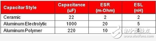
Table 1: Comparison of the three capacitors, each with advantages.
At low frequencies, all three capacitors do not exhibit parasitic components because the impedance is clearly only related to the capacitance. However, the impedance of the aluminum electrolytic capacitor stops decreasing and begins to exhibit resistance characteristics at relatively low frequencies. This resistance characteristic continues to increase until a certain relatively high frequency is reached (capacitor inductance). Aluminum polymer capacitors are another type of capacitor that does not match the ideal conditions. Interestingly, it has a low ESR and the ESL is obvious. Ceramic capacitors also have low ESR, but due to their smaller housing size, their ESL is less than aluminum polymer and aluminum electrolytic capacitors.
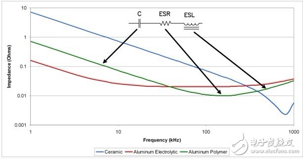
Figure 1. Parasitic changes in the impedance of ceramic, aluminum, and aluminum polymer capacitors.
Figure 2 shows the power supply output capacitor waveform for a continuous synchronous regulator simulation operating at 500kHz. It uses the main impedances of the three capacitors shown in Figure 1: ceramic capacitors; aluminum ESR; aluminum polymer ESL.
The red line is an aluminum electrolytic capacitor that is dominated by ESR. Therefore, the ripple voltage is directly related to the inductor ripple current. The blue line represents the ripple voltage of the ceramic capacitor, which has a small ESL and ESR. The ripple voltage in this case is part of the output inductor ripple current. Since the ripple current is linear, this results in a series of time-squared parts and looks like a sinusoid.
Finally, the green line represents the ripple voltage and its capacitor impedance is dominated by its ESL, such as aluminum polymer capacitors. In this case, the output filter inductor and ESL form a voltage divider. The relative phase of these waveforms is the same as we expected. When ESL dominates, the ripple voltage directs the output filter inductor current. When ESR dominates, the ripple is in phase with the current, and when the capacitor dominates, its delay. In reality, the output ripple voltage does not only contain voltages from one of these components. Instead, it is the sum of the voltages of all three components. Therefore, some parts of the ripple voltage waveform can be seen.
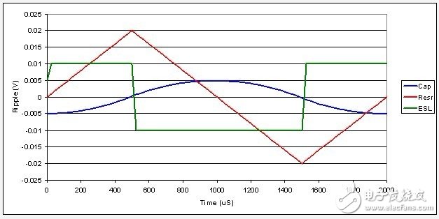
Figure 2 Capacitors and their parasitic elements form different ripple voltages in a continuous synchronous buck regulator
Figure 3 shows the waveform of a deep continuous flyback or buck regulator whose output capacitor current can be positive and negative, and the specific state will change rapidly. The red line clearly shows this, the voltage is multiplied by this current by ESR, and the result is a square wave. The voltage of the capacitor element is a component of the square wave. It causes linear charging and discharging, as shown by the blue triangle waveform. Finally, the voltage of the capacitor ESL is only apparent when the current changes during the transition. This voltage can be very high, depending on the output current rise time. Note that in this case, the green line needs to be divided by 10 (assuming a 25 nS current transition). These large inductor spikes are one of the many reasons for the frequent occurrence of two-stage filters in flyback or step-down power supplies.
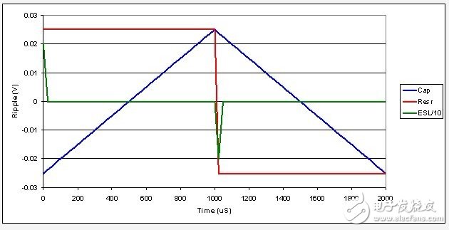
Figure 3 waveform changes with continuous flyback or buck output current
In summary, the impedance of the output capacitor helps to improve ripple and transient performance. As the frequency of the power supply increases, the impact of parasitic problems is greater and should not be ignored. Near 20 kHz, the ESR of an aluminum electrolytic capacitor is large enough to dominate the capacitive impedance. At 100 kHz, some aluminum polymer capacitors exhibit inductance. When the power enters the megahertz switching frequency, please pay attention to the ESL of all three capacitors.
Next time, we will discuss a low power, offline flyback converter, so stay tuned.
Current Fuse,Auto Fuse,Car Fuse,Blade Fuse
Dongguan Andu Electronic Co., Ltd. , https://www.idoconnector.com