In the transmission system of a car, if a mechanical manual transmission is used, it is generally equipped with a synchronizer, and its main function is to quickly synchronize between the sleeve and the ring gear to be engaged, and prevent the gear from meshing before synchronization. Prevents the impact between the engaging ring gears, shortens the shifting time, quickly completes the shifting operation, and extends the gear life.
This article refers to the address: http://
Synchronizer performance indicators directly affect the performance of the transmission, which affects the handling of the vehicle, so a series of related tests on its technical performance and life before installation.
The PLC-based transmission synchronizer test system can be used to perform real-time and accurate test recording of key parameters in the shifting process of the synchronizer. Through comparative analysis and processing, the performance and life of the tested synchronizer are objectively and accurately evaluated.
Because PLC has the characteristics of small size, strong function and high reliability, PLC is used as the control core of the whole test system. The drive motor simulates the shifting process and controls the speed of the two axes. At the same time, the computer is used to set the test conditions. It is used to collect multi-channel sensor signals in the test system at high speed, and perform post-analysis processing on the collected data, and issue corresponding instructions.
1 test system composition
The main components of the car synchronizer test system are: structural table body, variable frequency motor, servo motor, inertia flywheel, tested synchronizer, shifting manipulator, circulating lubrication system, manipulator control box, control cabinet, various detection sensors, PLC, Computer, etc., the mechanical structure of the test bench is shown in Figure 1.
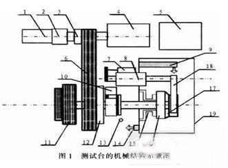
Note: 1. AC servo motor (0.85kW); 2. Reducer; 3. Clutch; 4. AC variable frequency motor (3 kW); 5. Robot hydraulic pump station; 6. Pulley; 7. Displacement sensor; Cylinder; 9. Lubricating oil injection port; 10. Encoder (low speed); 11. Combined inertia flywheel; 12. Clutch; 13. Speed ​​sensor (high speed); 14. Lubricating oil return port; 15. Two-component force Sensor; 16. gear cone; 17. synchronizer; 18. shift fork; 19. work compartment.
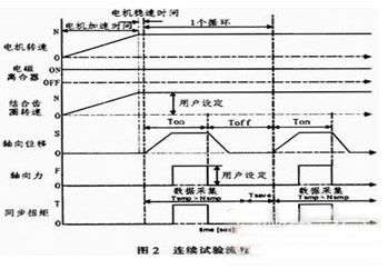
The test bench can perform three main tests on a certain type of synchronizer: continuous test, inertial test and squeeze test, continuous test and inertial test to measure the dynamic friction coefficient and wear resistance of the synchronizer, and the squeeze test is used to measure the synchronizer. Static friction coefficient, the test is carried out in the lubricating oil environment from room temperature to 120 °C. By analyzing and calculating the measurement data of the test bench, the synchronous friction performance and wear resistance are observed and recorded to evaluate the performance of the synchronizer. The continuous test process is shown in Figure 2.
2 test system design
The core of the whole test system is the measurement and control part. Firstly, it is required to monitor the operation status of the system in real time to ensure the safe and reliable operation of the system. At the same time, in the test process, it is required to collect the displacement, rotation speed, synchronous torque, axial force and lubricating oil in real time. A series of signal data such as gentle flow rate, through processing the collected signal data and the characteristic curve drawn therefrom, analyze and evaluate the relevant performance of the measured transmission synchronizer. The block diagram of the measurement and control system is shown in Figure 3.
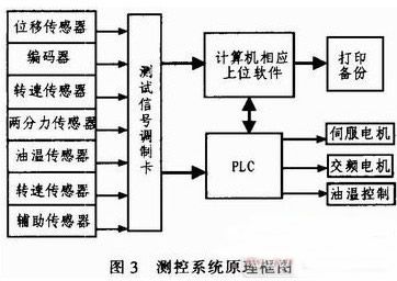
The measurement and control system consists of PLC, computer, various sensors, signal test conditioning card, drive and control motor. The test system is jointly controlled by the computer and PIC. The computer as a host computer has a good human-computer interaction function. It is responsible for monitoring the entire measurement and control system, sending commands and data to the PLC, realizing control of the field devices, and collecting by data analysis software. The test data is further processed to test the performance of the synchronizer.
Because PLC has the advantages of convenient operation and high reliability, it can meet the requirements of test system control well. Therefore, PLC is used to collect on-site signals and output control signals; it is responsible for direct control and monitoring of field devices, including motion control of shifting robots. The motor speed is adjusted, the transmission oil temperature is controlled, etc.; the sensor is responsible for collecting the signal of the scene, and the signal is converted into an analog quantity and transmitted to the PLC and the computer through the signal test conditioning card.
It should be pointed out that before the test starts, the gear position of the transmission must be preset, and the gear selection position sensor and the gear position sensor data corresponding to each gear are stored in the storage area of ​​the PLC, and the control of the robot is also controlled. Parameters such as the gear force of each gear, the gear speed, and the gear position compensation are stored in the storage area of ​​the PLC. During the test, the shift process is accurately and quickly simulated by quick query of these data.
3 system implementation
The measurement and control system is integrated with computer and PLC.
As the upper computer, the corresponding control program in the computer is developed based on the Windows2000/XP platform system. The user-friendly user interface can realize the automatic control of the test bench and the storage and analysis of the test data. The main functions of the test are:
1) Review, delete, analyze, and print historical test data or graphs;
2) Real-time display of the status of the equipment under test and possible error faults, and automatically respond to the error level (warning, error, serious error, fatal error);
3) The test program can be preset, including parameters such as axial force, loading time, unloading time, speed difference, lubricating oil temperature, etc., and can edit, save, download and print the synchronizer parameters and test conditions;
4) Continuously record relevant data in the test process continuously, display all measurement and calculation data in real-time graph, and generate corresponding change curve analysis map;
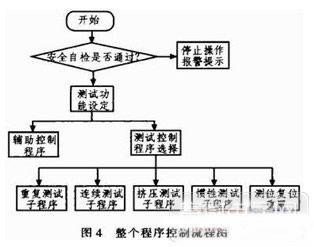
As the lower position machine, PLC is responsible for the control and monitoring of the field equipment. The control program in PLC is written by the TwinCAT PLC programming software of Beckhoff Company of Germany. The whole program control flow is shown in Figure 4.
The functions implemented by the control program in the PLC are mainly:
1) Collecting data Because there is usually strong electromagnetic interference in the test environment, if the corresponding anti-interference measures are not taken, it will enter the measurement and control system in the form of conduction and radiation, which will seriously affect the test results, so it should be correspondingly based on hardware and software. Processing, the corresponding electromagnetic shielding should be adopted on the hardware, multiple filtering circuits should be set in the test signal modulation card, and the I/O module of the PLC should be electrically isolated by photoelectric isolation function; the corresponding algorithm is used for filtering processing on the software to further reduce the interference effect. .
2) Safety protection When the improper operation or testing of the synchronizer parts assembly occurs prematurely or other faults (motor overload, overspeed, over temperature, etc.), the test rig can be automatically and automatically stopped, and the inverter has overcurrent, overload, Over-voltage, under-voltage, over-heat, short-circuit and cooling fan abnormal protection, overload and overspeed protection for the motor, overspeed, over-torsion and over-temperature protection for the system, all alarm signals display the cause of the fault or fault code through the main control computer; emergency Parking is a necessary hardware function, which can be performed manually or automatically. When the emergency stop is stopped, the loading mechanism is in the middle position. The motor stops urgently through the brake unit, the robot picks up the neutral gear, and the alarm sends an alarm.
3) The control shift PLC extracts the corresponding data in the storage area according to the control command sent by the computer, and performs the corresponding shifting action; at the same time, the computer monitors the completion of the shifting operation by reading the corresponding sensor signal, if the selection is not in place or When the shift is timed out, the neutral gear will be forced immediately to play the role of safety insurance; when the gear selection is timely and accurate, the next command will be issued.
4 Conclusion
The Synchronizer Test System is an automatic control electromechanical integration device that integrates signal acquisition and processing, electronic circuits, and mechanical structures. It can perform typical long-term, high-repetition test projects with stable and reliable operation. Level has important practical value.
Our circuit board manufacturing company has been serving high-tech fields such as electronic consumption, communication equipment, automotive electronics, power equipment, industrial control, medical care, security and military industry for a long time.
After establishment of more than 15 years,Liandajin always upholds the principle of "customer-centered and quality-oriented"to provide high-quality products and good services to customer.
6layers PCB Board,4Layers PCB,8layers PCB,Multilayer Curcuit Board,Multilayer Printed Circuit Board
Huizhou Liandajin Electronic Co., Ltd , https://www.ldjcircuitboard.com