Use NI's CompactDAQ hardware system and LabVIEW software to create a small thermal cycler with plug-and-play functionality of the USB interface to perform real-time polymerase chain reaction.
Polymerase chain reaction (PCR) thermal cycling is the gold standard for molecular diagnostics. However, the main challenge facing the global pandemic is that only professionals can conduct effective diagnostic tests. In addition, commercially available thermal cyclers can only be used in laboratory environments, so it is difficult to operate them, extending the application of commercial thermal cyclers to emergency situations, as well as to public inspection stations, such as The airport's cumbersome and expensive features are undoubtedly an obstacle. Therefore, there is an urgent need to develop a cheap, portable, and disposable molecular diagnostic tool.
To provide a flexible, cost-effective diagnostic system, our research team at the Singapore Institute of Bioengineering and Nanotechnology has developed a small diagnostic system using the PCR technology recommended by the Centers for Disease Control and Prevention (CDC). Detection of infectious diseases. Our system integrates and automates the entire diagnostic process from real-time PCR to detection of viral gene target strands to perform data analysis.
By using NI's CompactDAQ hardware system and LabVIEW graphical system design software for control and data analysis as our solution, we created a small, portable system. The system consists of a small Peltier (temperature device), a power supply (energy device), and a photodetector (optical device) with a USB interface plug and play function.
Our thermal cyclers are portable, fully automated, and can be used for large-scale health checks in critical settings, such as controlling the spread of infectious diseases at airport checkpoints. System automation is a key advantage of reliable diagnosis because a pandemic can occur in remote areas where there may be no trained personnel to process test samples. In addition, the implementation of system automation greatly reduces labor and training costs.
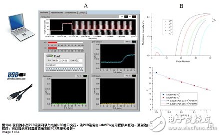
Using the system to run three polymers containing preloaded PCR reactants simultaneously takes less than an hour from sampling to results and allows for the use of a large variety of organisms. Using an internal temperature feedback of the thermistor, an internal proportional integral derivative (PID) chip is used to handle the temperature control. The controller consists of a compensator, output device and sensor feedback signals. The feedback signal is necessary to control the heater output power and maintain the temperature. Using LabVIEW software, we programmed the graphical user interface to display real-time temperature, set temperature, and display real-time PCR results from three channels (as shown in Figure 1A).
System Configuration
The entire integrated system configuration includes a cyclic temperature control system that performs the operation and reaction of the PCR system, three fixed blue LED light sources, and an associated lens for real-time optical detection between the LED and photomultiplier tube (PMT) optical paths. And filters. The system includes a set of heating chambers, either copper or brass, integrated with the polymer chamber where the sample is placed.
LabVIEW is the heart of the system architecture. The central processor unit is designed to execute instructions pre-written by LabVIEW and can be used to control system startup and health checks, thermal cycling control of PCR runs, and optical detection of multiplexed fluorescent signals.
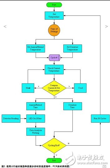
During the cyclic temperature control of the PCR process, the system performs optical detection at the last second of the annealing cycle. The three LEDs are simultaneously illuminated by the current drive from the NI 9265 analog output module, each LED illuminates for 200 ms, and the current LED is extinguished before the next LED is illuminated.
Specially designed devices are used to focus and direct LED light path transmission. Light passes through a filter before it is illuminated into the reaction chamber where the DNA sample is placed. The light passes through a series of lenses and filters before reaching the PMT, and the signal is finally read by the NI 9206 analog input module.
We use LabVIEW for signal processing to get the mean of the data set, and the signal from the PMT is amplified and processed. The data is then displayed to the user and continuously updated in three separate graphs via the main user menu (see Figure 2).
The PCR mixture was placed in a polycarbonate PCR reaction chamber and oiled to prevent evaporation. The PCR was carried out at the following temperature conditions: 95 ° C for 20 seconds (Taq polymerase activation), 50 cycles of amplification (heat denaturation at 95 ° C for 5 seconds, annealing at 60 ° C for 60 seconds) extend). The LabVIEW program records the fluorescence emitted by DNA replication in each cycle.
Stability and reusability
In molecular diagnostics, PCR is a common method of amplifying specific DNA fragments to the molecular level. In the implementation process, it is necessary to carry out thermal transformation of 40 to 50 cycles at 94 ° C, annealing at 60 ° C, and stretching at 60 ° C. The key point of the whole process is precise temperature control, maintaining a temperature rise rate of 2 °C / s to avoid generating or amplifying the wrong DNA sequence.
We used LabVIEW to control the independent high-side and low-side reference output channels, and designed and fabricated an on-chip heating scheme using a high-speed metal-oxide-semiconductor field-effect transistor (MOSFET) circuit to achieve real-time PWM control. Temperature measurements show that the heating and cooling rates we obtained were 2.5 °C/s and 2.2 °C/s, respectively. For each channel temperature setting, the overshoot is less than 1 °C and the stability is maintained at ±0.1 °C.
Results and conclusions
We used a 1 to 104 TaqMan probe to confirm the real-time detection performance of PCR by serial dilution of glyceraldehyde-3-phosphate dehydrogenase (GAPDH) complementary DNA (cDNA). The results confirmed that the sensitivity determined from the Ct curve was comparable to that of the real-time thermal cycler (Fig. 1B) on the market.
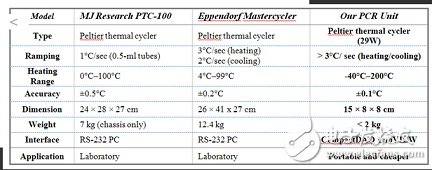
Compared to other thermal cyclers on the market, our systems are more compact, more portable and have better thermostat (Table 1). The portability of the system makes it play a bigger role in the early stages of a wide range of influenza outbreaks. At the same time, the diagnostic system is ideal for use in outpatient, emergency room, public inspection sites, etc. In addition, due to its portability, low price, small size, and ease of use, the thermal cycler has potential advantages in food safety.
Power Meter is a monitoring and testing instrument which determines the power consumption of a connected appliance and the cost of the electricity consumed.
Installing the batteries
Install 3.6V rechargeable Battcrics(NI-MH) . The purpose of the batteries is to store the total electricity and mcinory setting.
Resetting
If an abnormal display appears or the buttons produce no response, the instrument must be reset. To do this,press the RESET button.
Display Mode
Entire LCD can be displayed for about 1 minute and then it automatically gets into Model. To transfer from one mode to the other, press the FUNCTION button.
Mode 1: Time/Watt/Cost Display Display duration(how long) this device connect to power source.LCD on first line shows 0:00 with first two figures mean minutcs (2 figures will occur while occur at 10 min) and the rest shows seconds. After 60mins, it displays 0:00 again with first two numbers meas hour(2 figures will occur at 10hours) and the rest shows minutes. The rest can be done in the same manner which means after 24 hours, it will rc-caculatc. LCD on second line displays current power which ranges in 0.0W~9999W. LCD on third line displays the current electricity costs which ranges in 0.0cost~9999cost. It will keep on O.OOcost before setting rate without other figures.
Mode 2: l ime/Cumulative electrical quantity Display Display duration(how long) this device connect to power source.
LCD on first line shows 0:00 with first two figures mean minutes(2 figures will occur while occur at 10 min) and the rest shows seconds. After 60mins, it displays 0:0() again with first two numbers meas hour(2 figures will occur at 10hours)and the rest shows minutes. The rest can be done in the same manner which means after 24 hours, it will re-caculate. LCD on second line displays current cumulative electrical quantity which ranges in 0.000K WH 〜 9999KWII without other figures. LCD on third line displays''DAY''- "1 "will be showed on numerical part(thc other three figures will be showed at carry) which means it has cumulated electrical quantity for 24hours(one day). The rest can be done in the same manner untial the maximal cumulative time of 9999 days.
Mode 3: Time/Voltage/Frequency Display LCD on first line displays the same as Mode 1 dones. LCD on second line displays current voltage supply (v) which ranges in 0.0V~9999V .LCD on third line displays current frequency (HZ) which ranges in 0.0HZ~9999HZ without other figures.
Mode 4: Time/Current/Power Factor Display LCD on first line displays the same as Mode 1 dones.
LCD on second line displays load current which ranges in 0.0000A~9999A. LCD on third line displays current power factor which ranges in 0.00PF 〜 1 .OOPF without other figures.
Mode 5:Time/Minimum Power Display LCD on first line displays the same as Mode 1 clones. LCD on second line displays the miniinum power which ranges in 0.0W~9999W. LCD on third line displays character of "Lo" without other figures.
Mode 6: I,ime/Maximal Power Display LCD on first line displays the same as Mode 1 dones. LCD on second line displays the maximal power which ranges in 0.0W~9999W. LCD on third line displays character of "Hi" without other figures.
Mode 7: Time/Price Display LCD on first line displays the same as Mode 1 dones. LCD on third line
displays the cost which ranges in O.OOCOST/KWH 〜 99.99COST/KWH without
other figures.
Overload Display: When the power socket connects the load over 3680W, LCD on second line
displays the"O VER LOAD" with booming noise to warn the users,( 60470643,
60469303,selectable choice)
Supplemental informations:
1: Except tt OVERLOAD , ' interface, LCD on first line display time in repitition within 24hours.
2: LCD on first line, second line or third
line described in this intruction take section according to two black
lines on LCD screen. Here it added fbr clarified purpose.
3. Mode 7 will directly occur while press down button "cost".
4. [UP"&''Down" are in no function under un-setting mode.
Backlight Mode:
Connect to AC power,backlight im mediately light,if not press any button,backlight will went off in 15 seconds.
When press any of the buttonsbacklight
start light again. (Backlight only light when it connect to AC
power,backlight cannot light if use battery)
Setting Mode
1. Electricity price setting
After keeping COST button pressed lasting
more than 3 seconds(LCD on third line display system defaults price, eg
O.OOCOST/KWH ),the rendered content begins moving up and down which
means that the device has entered the setting mode. Then press FUNCTION
button to change selection and press UP/DOWN to set what you want. (On
pressing once, the figure after domical point will increase or decrease
accordingly. On pressing and hold-on, figures after demical point will
increase or decrease slowly in 2 seconds while figures change quickly
when hold-on time exceeds 2 seconds. When hold-on time reaches 10
seconds or more, the figures after demical point will stop while the
figures before demical point begin to increasing or decreasing.) After
that, press FUNCTION fbr swithing, then press [UP'nd "DOWN" button again
to set value which ranges in OO.OOCOST/KWH 〜 99.99COST/KWH. After
setting all above, press COST to return to Mode7 or it will
automatically return to Mode7 without any pressing after setting with data storage.
Power meter double rates, power meter two rates, cost rate socket, power meter cost rate, energy meter cost rate, cost socket, cost plug
NINGBO COWELL ELECTRONICS & TECHNOLOGY CO., LTD , https://www.cowellsocket.com