Generally speaking, the development process of an embedded system is as follows:
Identify the needs of embedded systems;
Design system architecture: Select processor and related external devices, operating system, development platform, and hardware and software partitioning and overall system integration;
Detailed hardware and software design and RTL code, software code development;
Joint debugging and integration of hardware and software;
System testing.
I. Step 1: Determine the requirements of the system:
The typical characteristics of embedded systems are user-oriented, product-oriented, and application-oriented. Market applications are the guiding and premise of embedded system development. The design of an embedded system depends on the needs of the system.
1, MVB bus introduction
Train CommunicaTIon Network (TCN) is an IEC international standard (IEC-61375-1) for train data communication that integrates internal measurement and control tasks and information processing tasks. It includes two types of bus types. Train bus (WTB) and multi-function car bus (MVB).
TCN's position in the train control system is quite similar to the status of the CAN bus in automotive electronics. The Multi-Function Vehicle Bus MVB is a standard communication medium for transferring and exchanging data between devices on a train. Devices attached to the bus may differ in function, size, and performance, but they are all connected to the MVB bus and exchange information over the MVB bus to form a complete communication network. In the MVB system, according to the IEC-61375-1 train communication network standard, the MVB bus has the following features:
Topology: The structure of the MVB bus follows the OSI model and draws on the ISO standard. Supports up to 4095 devices controlled by a central bus manager. Simple sensors and smart stations coexist on the same bus.
Data Type: The MVB bus supports three data types:
a. Process data: Process variables represent the state of the train, such as speed, motor current, and operator commands. The value of a process variable is called process data. Their transmission time is deterministic and bounded. To ensure this delay time, these data are transmitted periodically.
b. Message data: The message is divided into small packets, which are numbered and confirmed by the destination station. The message packet and its associated control data form the message data. Message data is transmitted as commands. The function message is used by the application layer; the service message is used for management of the train communication system itself.
c. Monitoring data: It is a short frame. The master device uses it for status check of devices in the same bus, detection of online devices, sovereign transmission, initial train operation and other management functions.
Media access form: MVB bus supports RS485 copper media and fiber. The data format of its physical layer is 1.5 Mbps serial Manchester encoded data.
Media access to the MVB is managed by the bus manager BA, which is the only bus master and all other devices are slaves. The master device periodically polls the ports in a predetermined order, during which the master device processes the sporadic requests.
Reliability measures: MVB fault tolerance measures include
Integrity of the transmission: The link layer has an extended error detection mechanism. The mechanism provides a Hamming code distance of 8, which can detect bit, frame and synchronization errors.
Failure independence: Copper media is usually fully configured in duplicate to ensure equipment failure independence.
Availability of delivery: Availability can be improved by means of media redundancy, power redundancy, and manager redundancy.
2. The basic requirements of the MVB system are as follows:
a. Fully compatible with IEC-61375-1 (TCN) international standards, supporting three data types of process data, message data, and monitoring data defined by the MVB bus.
b. The system is configurable to:
i. Bus Manager (BA) function
Ii. Bus Manager (BA) functions and communication functions
Iii. Independent communication function
c. Processor with ARM7TDMI
d. Using a real-time operating system
e. Real-Time Protocol Stack Protocol (RTP) for TCN
f. Support process data for 4096 logical ports
g. Support dual-port RAM interface with host PC104 host
h. Input voltage 5V
i. Working environment temperature: -40 ° C ~ 75 ° C
3. Other needs
The multi-function vehicle bus MVB system is designed in synchronization with the user's train control system and has strict time limits.
Second, step 2: design the system architecture, collaboratively allocate hardware / software requirements
The embedded system consists of two parts: hardware and software: the hardware architecture is centered on the embedded processor, and the necessary peripherals such as memory, I/O equipment, and communication module are configured. The software part is based on the software development platform and provides application programming upward. Interface (API), which blocks the board-level support package BSP for specific hardware features. In the embedded system, the software and hardware work closely together to coordinate the work and jointly complete the functions scheduled by the system. According to the seven-layer model of OSI, it can be determined that the link layer and the physical layer are implemented by hardware, and the other layers are implemented by software, as shown in FIG.
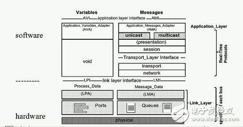
Figure 1: OSI model of MVB and hardware and software partitioning of MVB system.
1, embedded operating system selection:
In general, there are several factors to consider when choosing an operating system for an embedded system:
Operating system supported microprocessor
Operating system performance
Software components and device drivers for the operating system
Operating system debugging tools, development environment, in-circuit emulator (ICE), compiler, assembler, connector, debugger, emulator, etc.
Standard compatibility of the operating system
Technical support level of the operating system
Is the operating system providing source code or object code?
License usage of the operating system
Operating system developer reputation status
According to the requirements of the system and the above principles, the Vxworks real-time operating system is adopted in the MVB system. VxWorks is one of the real-time operating systems developed by Windriver. It is excellent in reliability, real-time and kernel. Sexuality is widely used in key industries such as communications, military, aerospace, aviation, industrial control, etc. Its development environment is Tornado.
2, the choice of processor:
There are several things to consider when choosing a processor for an embedded system:
Performance: The processor must have sufficient performance to perform tasks and support the product lifecycle.
Tool support: Support for software creation, debugging, system integration, code tuning, and optimization tools is critical to the success of the overall project.
Operating system support: Embedded system applications need to use helpful abstractions to reduce their complexity.
Developer's past processor experience: Experience with a processor or processor family can reduce the amount of time it takes to learn new processors, tools, and technologies.
Cost, power consumption, time to market, technical support, etc.
In the design of this system, taking into account the above factors, considering the processor performance, operating system support and the harsh industrial environment on the train, etc., ATMEL is used in the MVB system for industrial-grade AT91 in industrial control field. Series ARM processor AT91M40800, which is based on ARM7TDMI core, contains high performance 32-bit RISC processor, 16-bit high integration instruction set, 8KB on-chip SRAM, programmable external bus interface (EBI), 3-channel 16-bit counter / Timer, 32 programmable I/O ports, interrupt controller, 2 USARTs, programmable watchdog timer, main clock circuit and DRAM timing control circuit, and equipped with advanced energy-saving circuits; at the same time, support for JTAG debugging The main frequency can reach 40MHz.
3. Selection of related external equipment:
After determining the operating system and processor, you can determine the relevant external devices, such as FLASH, RAM, serial ports, and so on. In the MVB system, the MVB controller MVBC (MulTIfuncTIon Vehicle Bus Controller) is an interface controller between the MVB circuit and the actual physical device. Its main function is to realize the encoding and decoding of the MVB bus signal and data frame, error correction, etc. Function is the key hardware module to be implemented in this system. Due to system size, time to market, etc., the system does not consider ASIC implementation for the time being. Therefore, FPGA is used to implement this key module in MVB system. FPGA is the most flexible and cost-effective alternative to ASIC. Taking into account system requirements and FPGA resources, cost, availability and other factors, the choice of Altera's Cyclone series FPGA, the development tool is Quartus II.
4, MVB system architecture
From the above requirements analysis and selection, the complete system hardware architecture and software architecture are shown in Figure 2 and Figure 3.
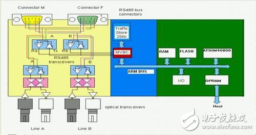
Figure 2: Hardware architecture of the MVB system.
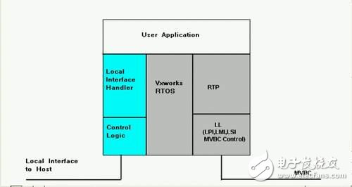
Figure 3: Software architecture of the MVB system.
Among them, the processor and MVBC exchange data through Traffic Memory (TM). All software and MVBC exchange control information and data can be found in the TM address space. This address space is accessible to both the processor and MVBC. . Its schematic 4 is as follows
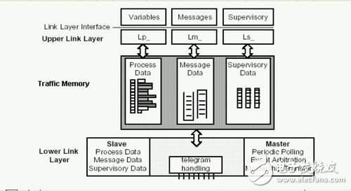
Figure 4: Traffic Memory.
Third, step 3: detailed hardware and software design and RTL code, software code development
Based on the system architecture, detailed hardware and software design can begin.
1, hardware design
The hardware design includes the FPGA design of the MVB controller and the board level design of the MVB bus system. The design of the key MVB controller is shown in Figure 5.
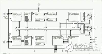
Figure 5: Block diagram of the MVB controller. (click to enlarge the picture)
As shown, the MVB controller contains the following functional modules:
Encoder: Generate Manchester encoding, transmit data frames
Transmit buffer: buffer as data to be sent and CRC detection value
Decoder: Receive, Manchester decoding, data extraction, data error detection
Receive buffer: buffer as the receiver data and CRC result
Message analysis unit: detecting primary frame and slave frame timeout, frame error detection, error status report
Status Control Register: MVBC Configuration
Main control unit: Support MVBC as master device or slave device, support queue message transmission
Device address reading and storage unit: Hardware-defined device address can be overwritten by different values
Address logic: parsing the input address of the CPU accessing the MVBC internal register; generating the output address of the MVBC access TM
Bus multiplexing, conversion unit: processing data transmission inside MVBC
Interrupt logic: support 16 interrupt sources;
General-purpose timer: two timing output signals that can be used to synchronize the system
Clock generation circuit: generates clocks and counters for all MVBC operations
2, software design
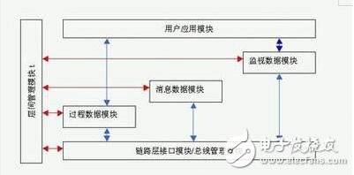
Since the process data, message data, and monitoring data are three different communication mechanisms in the MVB system, the module design of the MVB system software is shown in FIG. 6.
Fourth, the joint debugging and integration of software and hardware
Below, a simple example to illustrate the integration and verification of the hardware and software of the MVB system.
The process data is periodically transmitted in the MVB system, and its communication mechanism in the system is as follows: For the sender, the user application module sends a process variable of one port to the process data processing module, and the process data processing module follows the logical port. The setting timing updates the data of the corresponding logical port in the Traffic Memory through the link layer interface module, and the task of the sender software is completed. The MVBC hardware of the sender receives the main frame periodically sent by the bus manager BA, decodes the value of the corresponding logical port through the decoder, and automatically sets the MVBC to the sending state by querying the logical port related to the logical memory, and then sets the logic. The data of the port is sent as process data from the frame through the encoder, as shown in Figure 7:
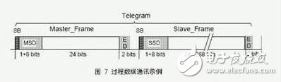
Figure 7: Example of process data communication.
For the receiver, the receiving process is opposite to the sender. The receiving MVBC hardware receives the main frame periodically sent by the bus manager BA, and decodes the value of the corresponding logical port through the decoder, and queries the logical port related to the Traffic Memory. After receiving the setting, the MVBC is automatically set to the receiving state. After receiving the slave frame sent by the sender, the data of the corresponding logical port in the Traffic Memory is updated and an interrupt signal is sent to complete the hardware receiving process. The receiver's software can obtain the updated process data of the logical port through the process data processing module by means of interrupt or timed query.
Fifth, the system test
In this system, the system test includes the software test, including the hardware, FGPA test, which will not be described in this article.
Conclusion
The above MVB system is now running in the train control system, successfully achieving train operation control, locomotive control, vehicle control, condition monitoring, and fault diagnosis. Of course, if necessary, the MVB system in this article can be transformed into an ASIC design, thus becoming an embedded system of SOC.
SMD: It is an abbreviation of Surface Mounted Devices. It is one of Surface Mount Technology (SMT) components. In the initial stage of circuit board production, through - hole assembly is completely manual. When the first automated machines were introduced, they could place some simple pin elements, but complex elements still needed to be placed manually for reflow soldering. Surface Mounted components mainly include rectangular chip components, cylindrical chip components, composite chip components and special-shaped chip components
Surface Mounted Devices
Changzhou Changyuan Electronic Co., Ltd. , https://www.changyuanelectronic.com