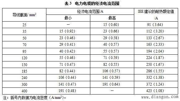
4.3 Economic current density of Table 2
The economic density values ​​in Table 2 are 1.83-3.84A/mm2, which is higher than the thermal rating recommended by IEE. It is close to the current density issued in 1956, so it cannot be called economic current density, but only the developer of initial investment. Favorable current density.
The so-called hybrid insulation means that the busbars are heat-shrink-insulated and then placed in the housing at intervals, and air insulation is added between the busbars. The hybrid insulated busway can only be classified into the radiation heat dissipation, and the heat dissipation effect is definitely worse than the dense busway with conduction heat dissipation. Therefore, the data provided in Table 2 is not obtained through scientific experiments, but is based on the data of the sample. There is an error.
At the end of the literature, "the economic current density calculation shows that the economic current density of the busway is large. Therefore, the economic current density of the busway is larger than the economic current density of the transmission line promulgated by the Ministry of Water and Electricity in 1956. Therefore, the busbar slot You should use your own economic current density value." This is a very different conclusion from the results in Table 3. The reason for this phenomenon is due to the inconsistency between the author's views of the literature and the best cross-sections currently advocated.
5 Conclusion
According to the samples provided by the busbar manufacturer, the current density corresponding to the rated current value only satisfies the thermal stability test, not the economic current density. According to the current situation in China, taking 1/2 of the rated current of the busway may be closer to the optimal section.
A membrane switch consists of various layers laminated together. The layers of a basic membrane switch construction include: a membrane overlay, spacer, printer circuit, rear adhesive, and tail filler. Depending on the environment and requirements of the application into which the membrane switch plugs into, the construction can vary.
Membrane Switch Assemblies,Lcd Display Membrane Switch,Tactile Membrane Switch Keypad,Overlay Tactile Membrane Switch
KEDA MEMBRANE TECHNOLOGY CO., LTD , https://www.kedamembrane.com