Realize the function: 1, the panel starts and stops, the given frequency
2, the resistance given frequency, switch positive and negative
3, fixed frequency
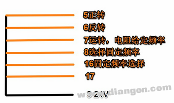
The figure above shows the schematic diagram of the MM440 digital input. The yellow lines are all controlled by the switch (I have drawn a switch, what software is used to draw the circuit diagram? I don't remember)
P0700ã€0】: Select command source (start/stop)
=1 BOP
=2 I/O terminal control
P01000ã€0】: Set the frequency reference source
=1 BOp motor potentiometer given
=2 analog input 1 channel (terminals 3, 4)
=3 fixed frequency
P0811 P0810
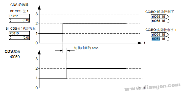

P0810 is associated with r0054, P0811 and r0055 are associated with the first set of parameters, the second set of parameters, and the third set of parameters.
P700(0)=1 P700(1)=2 P700(2)=2
P1000(0)=1 P1000(1)=2 P1000(2)=3
P0701(0)=0 P701(1)=1 P701(2)=1
P0702(0)=0 P702(1)=2 P702(2)=2
P0703(0)=99 P704(1)=99 P705(2)=15
P810=722.2 P811=722.3 P1005(2)=Required fixed frequency
722.2 corresponds to Din3, that is, terminal No. 7.
722.3 corresponds to Din4, that is, terminal No. 8.
After the switch corresponding to terminal No. 7 is closed, P810 is valid (I understand that it can be operated, set to 1), and it is switched to the second group of parameters by dcs in the above figure; after the switch corresponding to terminal No. 8 is closed, P811 is valid. Switch to the third set of parameters. (If there is no error in the memory, when the second group of parameters is running, in the case of the motor running, close the terminal switch No. 8, and then set the frequency, you can switch directly)
Wenzhou Niuniu Electric Co., Ltd. , https://www.anmuxisocket.com