Abstract: This paper introduces the DC motor control system with TL494 as the core and PWM technology. The H-bridge DC motor control system based on TL494 can simplify circuit structure, strong driving capability, low power consumption, convenient control and stable performance.
Due to its good starting, braking and speed regulation performance, DC motors have been widely used in various fields such as industry and aerospace. With the development of power electronics technology, pulse width modulation (PWM) speed regulation technology has become a commonly used speed control method for DC motors, featuring high speed regulation accuracy, fast response speed, wide speed range and low power consumption. The power drive circuit with the H-bridge circuit as the driver can conveniently realize the four-quadrant operation of the DC motor, including forward rotation, forward rotation braking, reverse rotation and reverse rotation. It has been widely used in modern DC motor servo systems. .
1. DC motor PWM speed control principleAs we all know, the DC motor speed formula is:
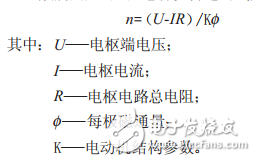
DC motor speed control can be divided into excitation control method and armature voltage control method. Excitation control is used sparingly, and armature voltage control is used in most applications. With the advancement of power electronics technology, changing the armature voltage can be achieved in a variety of ways, of which pulse width modulation (PWM) is a commonly used method of changing the armature voltage. The method is to adjust the armature voltage U of the DC motor by changing the ratio of the on-time of the motor armature voltage to the energization period (ie, the duty ratio), thereby controlling the motor speed.
The core component of PWM is a voltage-to-pulse width converter, which functions to modulate the pulse width according to the control command signal, so as to control the on-time of the high-power transistor with the pulse signal whose width varies with the command, thereby realizing the two armature windings. Terminal voltage control.
The voltage-pulse width converter structure is shown in Fig. 1, and is composed of a triangular wave generator, an adder and a comparator. The triangular wave generator is used to generate a triangular wave UT of a certain frequency, which is added by the adder to the input command signal UT to generate a signal UI+UT, which is then sent to the comparator. The comparator is an op amp that operates in an open-loop state with extremely high open-loop gain and limiting switching characteristics. A slight change in the signal difference between the two inputs causes the comparator to output a corresponding switching signal. In general, the comparator's negative input is grounded and the signal UI+UT is input from the positive terminal. When UI+UT is 0, the comparator outputs a positive level of full amplitude; when UI+UT is 0, the comparator outputs a negative level of full amplitude.
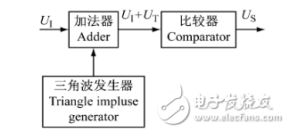
Figure 1 voltage-pulse width comparator
The modulation process of the signal waveform by the voltage-pulse width converter is shown in Fig. 2. Due to the limiting characteristics of the comparator, the amplitude of the output signal Us does not change, but the pulse width varies with the UI. The frequency of Us is determined by the frequency of the triangular wave.
When the command signal UI=0, the output signal Us is a rectangular pulse having equal positive and negative pulse widths. When UI is 0, the positive pulse width of Us is greater than the negative pulse width. When the UI is 0, the positive pulse width of Us is smaller than the negative pulse width. When UI is UTPP/2 (UTPP is the peak of the triangle wave), Us is a positive DC signal; when UI is UTPP/2, Us is a negative DC signal.
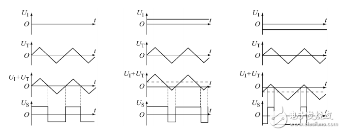
Figure 2 PWM pulse width modulation waveform
Charging Pile Energy Management Solution
Charging Pile Energy Management Solution,Charging Pile DC Energy Meter,Charging Pile AC Energy Meter,Bidirectional DC Energy Meter,Electric Car Charging Pile Energy Meter
Jiangsu Acrel Electrical Manufacturing Co., LTD. , https://www.acrel.com.pk