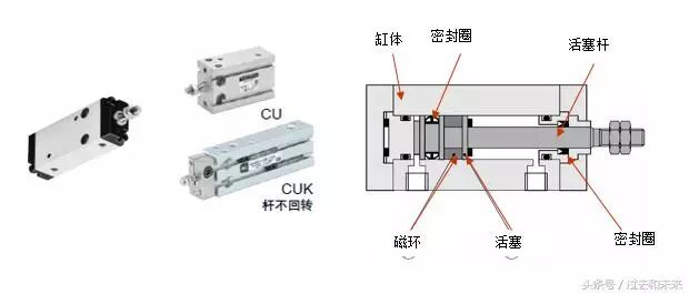
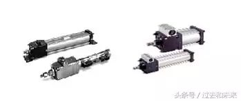
We first explain the basic composition and principle of the ordinary cylinder:
The composition of the cylinder: cylinder, piston, seal, magnetic ring (cylinder with sensor)
Principle: The pressurized air moves the piston and changes the direction of movement of the piston rod by changing the direction of the intake.
Failure mode: The piston is stuck, does not move; the cylinder is weak, the seal is worn, and the air leaks.
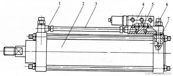
Typical cylinder structure and working principle
Taking the single-piston double-acting cylinder most commonly used in pneumatic systems as an example, the typical structure of the cylinder is shown in the figure below. It consists of a cylinder, a piston, a piston rod, a front end cover, a rear end cover and a seal. The inside of the double-acting cylinder is divided into two chambers by the piston. There is a rod cavity called a rod cavity, and a pistonless cavity is called a rodless cavity.
When the compressed air is input from the rodless chamber, the rod chamber is exhausted, and the pressure difference between the two chambers of the cylinder acts on the piston to overcome the resistance load to push the piston to move, so that the piston rod extends; when there is a rod chamber, When the rodless chamber is exhausted, the piston rod is retracted. If there is a rod chamber and a rodless chamber alternately intake and exhaust, the piston realizes a reciprocating linear motion.
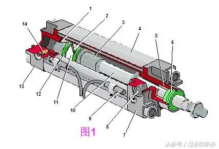
Ordinary double-acting cylinder
1, 3-buffer plunger, 2-piston, 4-cylinder, 5-guide sleeve, 6-dust ring, 7-front cover, 8-port, 9-sensor, 10-piston rod, 11- wear resistant Ring, 12-seal, 13-rear cover, 14-buffer throttle
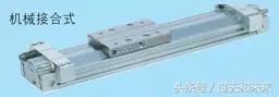
Structure and working principle of mechanical contact rodless cylinder
The mechanical contact type rodless cylinder has the structure shown in Figure 3 below. A groove is formed in the axial direction of the cylinder tube, and the piston and the slider move in the upper part of the groove. In order to prevent leakage and dustproof, a polyurethane sealing tape and a dustproof stainless steel tape are fixed on the cylinder heads at both ends of the opening, and the piston frame passes through the groove to integrally connect the piston and the slider. The piston is coupled to the slider to drive the actuator fixed to the slider to reciprocate.
The characteristics of this type of cylinder are: 1) Compared with ordinary cylinders, it can reduce the installation position by 1/2 under the same stroke; 2) It does not need to set anti-rotation mechanism; 3) It is suitable for cylinder diameter 10~80mm, the maximum stroke is cylinder diameter ≥ Up to 7m at 40mm; 4) High speed, standard type can reach 0.1~0.5m/s; high speed type can reach 0.3~3.0m/s. The disadvantages are: 1) poor sealing performance, easy to produce external leakage. The medium pressure type must be used when using the three-position valve; 2) The load force is small, and in order to increase the load capacity, the guide mechanism must be added.
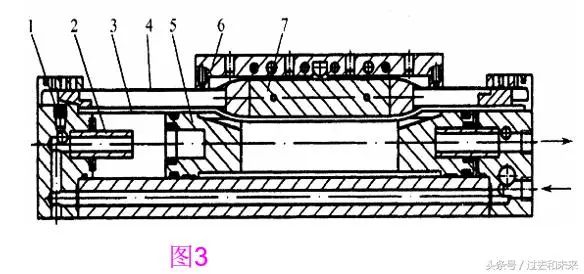
Mechanical contact rodless cylinder
L-throttle valve, 2-buffer plunger, 3-sealing belt, 4-dust stainless steel belt, 5-piston, 6-slider, 7-piston
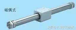
Structure and working principle of magnetic rodless cylinder
The piston drives the moving body outside the cylinder to move synchronously by magnetic force, and its structure is as shown in FIG. 4 . It works by installing a set of high-strength magnetic permanent magnets on the piston. The magnetic lines of force pass through the thin-walled cylinder and the other set of magnetic rings that are placed outside. Since the two sets of magnetic rings have opposite magnetic properties, they have strong suction. . When the piston is pushed by the air pressure in the cylinder, the magnetic ring sleeve outside the cylinder is moved together under the action of the magnetic force. The thrust of the cylinder piston must be adapted to the suction of the magnetic ring.
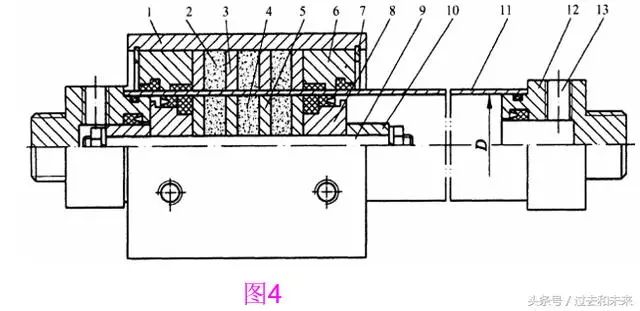
Magnetic rodless cylinder
1-sleeve, 2-outer magnetic ring, 3-external magnetic guide plate, 4-inner magnetic ring, 5-inner magnetic guide plate, 6-gauge cover, 7-snap ring, 8-piston, 9-piston shaft, 10- Buffer plunger, 11-cylinder, 12-end cap, 13-in, exhaust
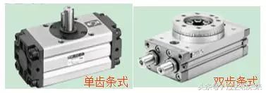
Structure and working principle of rack and pinion swing cylinder
The rack and pinion type oscillating cylinder is a kind of oscillating cylinder which rotates the gear by a rack connected to the piston, and its structural principle is as shown in FIG. 5. The piston only makes reciprocating linear motion, the friction loss is small, and the efficiency of the gear transmission is high. The efficiency of the swinging cylinder can reach about 95%.
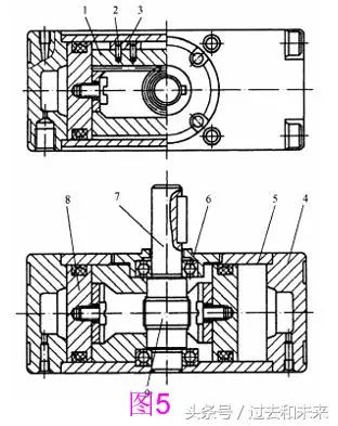
Rack and pinion swing cylinder
1-rack assembly, 2-spring pin, 3-slider, 4-end cover, 5-cylinder, 6-bearing, 7-axis, 8-piston, 9-gear
Blade type swing cylinder and working principle
The structural principle of the single-blade swing cylinder is shown in Fig. 6. It consists of a blade shaft rotor (ie output shaft), a stator, a cylinder block and front and rear end caps. The stator and the cylinder are fixed together, and the blades and the rotor are coupled together. There are two gas paths on the stator. When the left side is in the air, the right side is exhausted, and the compressed air pushes the blades to drive the rotor to swing clockwise. Conversely, swing counterclockwise.
The blade type swing cylinder has small volume and light weight, but the manufacturing precision is high, the sealing is difficult, the leakage is large, and the dynamic sealing contact area is large, the friction resistance of the sealing member is large, and the output efficiency is low, less than 80%. Therefore, it is limited in application, and is generally only used when the installation position is limited, such as the rotation of the clamp, the opening and closing of the valve, and the indexing of the table.
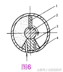
Single vane swing cylinder
1-blade, 2-rotor, 3-stator, 4-cylinder
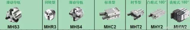
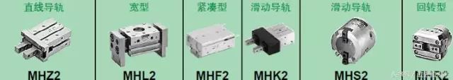
Pneumatic gripper principle
Pneumatic gripper This actuator is a variant cylinder. It can be used to grab objects and achieve various actions of the robot. In automated systems, pneumatic grippers are often used to pick and place objects in handling and transporting workpiece mechanisms.
Pneumatic gripper has parallel opening and closing fingers (as shown), toggle swivel opening and closing claws, two claws, three claws and four claws. Among them, there are flat and fulcrum opening and closing driving modes in the two claws. Available in linear and rotary styles.
The opening and closing of the pneumatic hand is generally driven by a reciprocating linear motion generated by the cylinder piston to drive a crank connecting rod, a roller or a gear connected to the claw, and drive each of the claws to open and close simultaneously.
The structure and working principle of the membrane cylinder
The figure below shows the working principle of the diaphragm cylinder. The diaphragm has a flat diaphragm and a disc diaphragm, which are generally made of a woven fabric rubber, a steel sheet or a phosphor bronze sheet, and have a thickness of 5 to 6 mm (using a 1 to 2 mm thick diaphragm).
The diaphragm cylinder shown in the figure below functions like a spring-returned piston-type single-acting cylinder. During operation, the diaphragm pushes the piston rod under compressed air. The utility model has the advantages of simple structure, compactness, small volume, light weight, good sealing performance, low air leakage, simple processing, low cost, no wear parts, convenient maintenance, etc., and is suitable for occasions with short strokes. The disadvantage is that the stroke is short and generally does not exceed 50mm. The flat diaphragm has a shorter stroke of about 1/10 of its diameter.
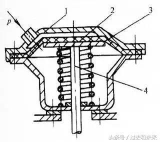
Film cylinder
1-cylinder, 2-diaphragm, 3-membrane, 4-piston rod
Structure and working principle of cylinder with valve combination
The valved cylinder is a combined pneumatic actuator consisting of a cylinder, a reversing valve and a speed control valve. As shown in the figure below, it eliminates the need to connect pipes and pipe joints, reduces energy loss, and has the advantages of compact structure and convenient installation. Valves with valve cylinders have various control modes such as electric control, air control, machine control and manual control. The valve is installed in the rear of the cylinder, the upper part and so on. As shown in the figure below, the electromagnetic reversing valve is installed in the upper part of the cylinder. When there is an electric signal, the solenoid valve is switched, and the output air pressure can directly control the cylinder action.
Valve combination cylinder
1-pipe joint, 2-cylinder, 3-air pipe, 4-electromagnetic reversing valve, 5-way valve bottom plate, 6-way one-way throttle valve assembly, 7-seal ring.
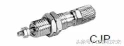
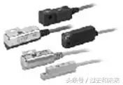
Structure and working principle of magnetic switch cylinder
The magnetic switch cylinder means that a magnetic ring is mounted on the piston of the cylinder, and a magnetic switch is directly mounted on the cylinder. The magnetic switch is used to detect the position of the cylinder stroke and control the reciprocating motion of the cylinder. Therefore, it is not necessary to install a stroke valve or a stroke switch on the cylinder to detect the position of the cylinder piston, and it is not necessary to provide a stopper on the piston rod.
Its working principle is shown in the figure below. It is equipped with a permanent magnetic ring on the cylinder piston and a reed switch on the cylinder housing. The switch is equipped with a reed, a protection circuit and an action indicator, all of which are molded in a box with resin. When the piston with the permanent magnet moves to the vicinity of the tongue, the magnetic flux is magnetized by the tongue, and the two springs are attracted to contact, and the switch is turned on. When the permanent magnet returns to leave, the magnetic field weakens and the two reeds spring open, the switch opens. Since the switch is turned on or off, the solenoid valve is reversed to achieve the reciprocating motion of the cylinder.
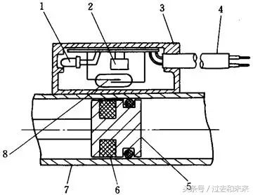
Magnetic switch cylinder
1-action indicator, 2-protection circuit, 3-switch housing, 4-wire, 5-piston, 6-magnetic ring, 7-cylinder, 8-reed switch
Select Vape presents Bang xxl Switch DUO Disposable Device. Experience a mouthwatering sensation of two exquisite flavors packed in one disposable device wherever you go. The Bang XXL Switch DUO provides a 7ml (3.5ml/per flavor) juice capacity powered by an integrated 1100mAh non-rechargeable battery, delivering amazing flavor output. This device is operated via draw-activated firing mechanism and you can switch between flavors by using the switch located at the base. Each Bang XXL contains 6% nicotine and lasts roughly 2000~ puffs before disposal.
Designed for those who are always on the go, the Big Bang XXL Switch Duo Disposable Vape is an ultra-advanced vaping pod mod system that`s all about giving a rapidly smooth puff trip to all the meshuga vapers! This smart and compact mechanism of vaping will leave you with the perfect ` larger than life throat hits` without actually demanding anything. These pre-filled, pre-charged, vaping throwaways beat the rest for their unique blend of sleek designing yet giving vapers the double extra large puff feels!
To top it all is the flavor switching feature with an exquisite combination of tastes giving our taste buds an awesome flavor experience. The smart and sleek vape juice composition holds 6% of concentrated nicotine salt in the e-juice. The good news is that they are absolutely low maintenance! Slide your hand in the pocket and you are set for the extravagant 2000 flavor-rich,mess-free puffs!
FLAVOR PROFILE:
BANANA ICE/STRAWBERRY BANANA
COOL MINT/BLUEBERRY ICE
RED APPLE/GREEN APPLE
STRAWBERRY ICE/WATERMELON ICE
WATERMELON LUSH/BUBBLEGUM
STRAWBERRY APPLE WATERMELON/STRAWBERRY KIWI
BLUE RAZ/RED RAZ PASSION
VERY BERRY/GUMMY BEAR
disposable vape pen. bang xxl vape, vape disposable ,double flavor vape
Shenzhen Essenvape Technology Co., Ltd. , https://www.essenvape.com