The regulated power supply generally consists of three parts: a transformer, a rectifier, and a voltage regulator. The transformer changes the mains AC voltage to the required low voltage AC. The rectifier turns the alternating current into direct current. After filtering, the regulator then turns the unstable DC voltage into a stable DC voltage output.
First, the technical indicators of the regulated power supply and the requirements for the regulated power supply
The technical specifications of the regulated power supply can be divided into two categories: one is the characteristic index, such as the output voltage, the output filter and the voltage adjustment range; the other is the quality indicator, which reflects the advantages and disadvantages of a regulated power supply, including stability. , equivalent internal resistance (output resistance), ripple voltage and temperature coefficient. For the performance of the regulated power supply, there are mainly the following four aspects.
1. Good stability
When the input voltage Usr (rectified, filtered output voltage) varies within a specified range, the change in output voltage Usc should be small as a general requirement.

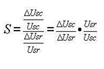
The degree of change in output voltage due to input voltage variation, called the stability index, is commonly used to indicate the magnitude of S, which reflects the ability of a regulated power supply to overcome input voltage changes. Under the same input voltage variation condition, the smaller S is, the smaller the change of the output voltage is, and the higher the stability of the power supply. Usually S is about.
2. Small output resistance
When the load changes (from no load to full load), the output voltage Usc should remain basically unchanged. The performance of this regulated power supply can be characterized by the output resistance.
The output resistance (also known as equivalent internal resistance) is expressed in rn, which is equal to the ratio of the amount of change in output voltage to the amount of change in load current.

Rn Reflects the ability of the output voltage to remain constant when the load changes, and the smaller the rn, the smaller the change in output voltage when Ifz changes. A regulated power supply with excellent performance, the output resistance can be as small as 1 ohm or even 0.01 ohm.
3. The voltage temperature coefficient is small
When the ambient temperature changes, it will cause the output voltage to drift. A good regulated power supply should effectively suppress the drift of the output voltage when the ambient temperature changes, keep the output voltage stable, and the output voltage drift is expressed by the temperature coefficient KT.
4. The output voltage ripple is small
The so-called ripple voltage refers to the AC component of 50 Hz or 100 Hz in the output voltage, usually expressed by an effective value or a peak value. After the voltage regulation, the ripple voltage after rectification and filtering can be greatly reduced, and the reduced multiple is inversely proportional to the voltage regulation coefficient S.
The series regulator circuit introduced in the previous section is used as a simple regulated power supply to meet the needs of general radio enthusiasts. However, there are many "born" defects in this type of power supply. To improve performance requirements, some improvements must be made. From the following four right to improve its performance, you can make a practical power supply. This is: increase the amplification link, improve the stability, make the output voltage adjustable; use the composite tube as the adjustment tube to increase the output current; increase the protection circuit to make the power supply work safely and reliably.
Second, the power supply with amplification
The variation of the output voltage ΔUsc is very weak, and its control effect on the adjustment tube is also weak, so the voltage regulation effect is not good enough. The regulated power supply with the amplification section is to add a DC amplifier to the circuit, which is weak. The output voltage variation is first amplified, and then the control tube is controlled to improve the control of the adjustment tube, so that the stability of the regulated power supply can be improved. Figure 5-22 shows a regulated power supply circuit with an amplification section.
In the figure, BG1 is the adjustment tube and BG2 is the comparison amplification tube. A part of the output field change amount ΔUsc is compared with the reference voltage Uw, and amplified by BG2 to reach the base of BG1. Rc is the collector resistance of BG2 and the upper bias resistor of BG1. R1 and R2 are the upper and lower bias resistors of BG2, which form a voltage dividing circuit. A part of ΔUsc is sampled as an output voltage and sent to the base of BG2.
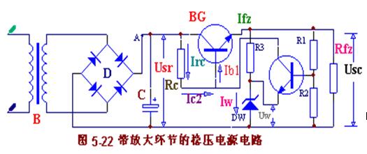
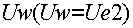
The voltage Ub2 on the sampling circuit R2 is called the sampling voltage. The DW and R3 groups form a voltage regulator circuit that provides a reference voltage.
It can be seen from the circuit path that when the output voltage Usc falls, the base potential Ub2 of BG2 also drops by the action of the voltage dividing circuit composed of R1 and R2. Since the reference voltage UW keeps the emitter potential of BG2 constant, Ubc2 := Ub2, a UW decreases. Then, the collector current Ic of the BG2 is decreased, and Uc2 is increased, that is, the base potential Ub1 of BG1 is increased, the Icl is increased, and the tube voltage drop Uce1 is decreased, so that the output voltage Usc remains substantially stable. The larger the magnification of BG2, the stronger the adjustment and the more stable the output voltage.
If the output voltage Usc is increased, the same reason, the feedback will be used to reduce the Usc, keeping the output voltage substantially unchanged.
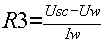
Let's talk about the selection principle of each component. As mentioned earlier, Rc is the load resistance of the amplifier stage and is equivalent to the bias resistance of the regulator. Rc is large and the amplification factor is large, which is beneficial to improve the regulator index. However, the Rc is too large to make the BG2 and the regulating tube current too small, which limits the load current and the adjustment range. Usually Rc is selected according to the following formula:
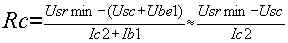
Usrmin is the minimum voltage at which the output is rectified. Ic2 can take 1 to 3 mA. The stable voltage Uw of the Zener diode DW has a wide selection range as long as the BG2 is not saturated (that is, Uw is less than 2 volts lower than Usc). Uw is large, the sampling voltage can be larger, which is beneficial to improve the voltage regulation performance. The current I3 through which the current limiting resistor R3 passes should be equal to the stable current of the DW, which should satisfy the following relationship:
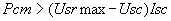
The input voltage Usr should be greater than the output voltage Usc by 3 to 8 volts. If the Usr is too small, the adjustment tube is easy to saturate and does not adjust. If the Usr is too large, the tube is depleted and power is wasted. The rectification ripple is small, and the Usr can be lower. If the ripple is large, the Usr should be higher. Adjust the beta value of tube BG1 as large as possible, for which you can use the duplicate tube. The power consumption of the adjustment tube should also be large enough to meet the following requirements:
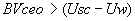
Usrmax is the rectified output voltage at the highest grid voltage. The tube BG2 should also be used with a tube with a large β value to enhance the control of the adjustment tube and make the output more stable. In the larger voltage regulator circuit of Usc, you should also pay attention to the reverse voltage that BG2 can withstand.
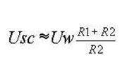
Transistor. The voltage divider resistor (R1+R2) should be appropriately small to improve circuit performance. Usually, the current flowing through the voltage dividing resistor is greater than 5-10 times the base current of the amplifying tube. The voltage division ratio is determined by the output voltage Usc and the reference voltage Uw, which is determined by:
Generally, R1 or R2 can be selected first, and then another resistor can be adjusted by calculation. The partial pressure ratio should be selected to be larger, generally 0.5 to 0.8.
Third, the output voltage adjustable power supply
As can be seen from the above circuit, the relationship between the output voltage and the reference voltage is "provisioned" by the voltage divider circuit. When the reference voltage is constant, changing the voltage division ratio can change the output voltage within a certain range. in
Adding a potentiometer W between R1 and R2 (see Figure 5-23), the output voltage can be continuously adjusted within a certain range.
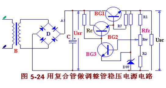
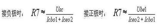
Fourth, the composite tube is used as the regulated power supply of the regulating tube. In the regulated power supply, the load current Ifz should flow through the adjusting tube. The power supply for outputting a large current must use a high-power adjusting tube, which requires a large enough current supply adjustment. The base of the tube, and the comparison amplifier circuit can not supply the required large current. On the other hand, the adjustment tube needs to have a higher current amplification factor to effectively improve the voltage regulation performance, but the high power tube generally does not have a current amplification factor. high. The solution to these contradictions is to equip the original adjustment tube with one or more "assistants" to form a composite tube. The stabilized power supply circuit using the composite pipe as the adjusting tube is shown in Fig. 5-24.
When the composite tube is used as the adjusting tube, the reverse current Iceo2 of BG2 will be amplified. Especially when the high power manifold is used, the reverse cutoff current Icbo is relatively large, and increases exponentially with increasing temperature, which easily causes high temperature and no load. The out of control of the regulated power supply increases the output voltage Usc. The error signal ΔUsc is amplified to the base of BG2 to reduce the Ic, possibly forcing BG2 to turn off. In order to make the adjustment tube work in the amplification area at different temperatures, the base plus resistance (R7) of BG1 is often connected to the positive pole of the power supply (as shown in Figure 5-24) or the negative pole. This resistance may not be added when the temperature or load does not change much or when the silicon tube is used in its entirety.
The value of R7 can be approximated by the following formula:
5. Regulated power supply with protection circuit.
In the voltage regulator circuit, short circuit protection measures must be taken to ensure safe and reliable operation. Ordinary fuses are blown slowly, and the fuse is not used to protect them. A protective circuit must be installed.
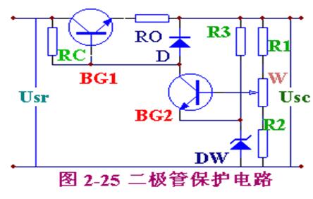
The function of the protection circuit is to protect the tamping tube from being burnt when the circuit is short-circuited and the current is increased. The basic method is that when the output current exceeds a certain value, the adjustment tube is in a reverse bias state, thereby being turned off, and the circuit current is automatically cut off. There are many forms of protection circuits. Figure 2-25 shows the diode protection circuit, which consists of diode D and sense resistor R0 of diode protection circuit 2-25. During normal operation, although the voltage across the diode is low, the diode is still in the reverse state. When the load current increases to a certain value, the depression ROIe on the resistor RO is increased to turn on the diode. Since UD=Ube1+ROIe and the on-voltage UD of the diode is constant, Ube1 is forced to decrease, so that Ie is limited to a certain value to achieve the purpose of protecting the adjustment tube. When using, the diode should use a large UD value.

Figure 2-26 shows the triode protection circuit. It is composed of a transistor BG2 and voltage dividing resistors R4 and R5. When the circuit works normally, the base potential of BG2 is higher than the emitter potential through the pressure of R4 and R5, and the emitter junction is subjected to the reverse voltage. Therefore, BG2 is in the off state (equivalent to an open circuit) and has no effect on the voltage regulator circuit. When the circuit is short-circuited, the output voltage is zero, and the emitter of BG2 is equivalent to ground. Then, BG2 is in a saturated conduction state (corresponding to a short circuit), so that the base and emitter of the adjustment tube BG1 are nearly short-circuited, and are in an off state. Cut off the circuit current for protection purposes.
HIFU Piezoelectric Ceramic Parts
High Intensity Focused Ultrasound (HIFU) technology is to focus ultrasound on a single point to produce high energy, function on the dermis and SMAS layer of skin, stimulate the proliferation and recombination of collagen, effectively achieve the effect of compact contour and smoothing lines.
Focused ultrasound does not heat the skin surface, nor does it need to pass through the skin as a medium for the transmission of laser energy, so it does not affect the tissue on the skin surface and the tissue through which the laser passes, of course, there will be no excessive heat residue on the skin surface. In this way, the epidermis will not be affected by heat, which can reduce the Eastern people's thermal reaction easily, and greatly reduce the chance of scald. Focused ultrasoundtherapy produces thermal coagulation points in the SMAS layer, and the thermal effect diffuses outward from the coagulation points, so the heat source is concentrated in the SMAS layer to be treated. It can produce more collagen denaturation.
Ultrasonic Transducer Component,Piezo Crystal For Vibration Transducer,Piezoelectric Ultrasonic Rings,High Power Ultrasonic Machining
Zibo Yuhai Electronic Ceramic Co., Ltd. , https://www.yhpiezo.com