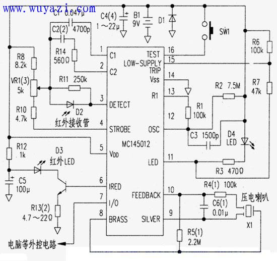
The fire alarm integrated circuit MC145012 integrates all the functions of the alarm. As long as the external infrared emission, receiving components and speakers are connected, it can form a fire alarm, and can also be connected with the computer to form an alarm system.
Circuit principle. The infrared LED (D3) is driven by the 6-pin output to emit infrared light, which is received by the infrared receiving tube D2: D2 and D3 are installed in positions that are not directly opposite each other. When there is no smoke caused by fire, the D2 output is 0; if there is smoke, the infrared light is scattered by the smoke, so that D2 can receive the scattered light and trigger the alarm.
In Figure 2, adjusting the values ​​of C2 and R13 can roughly adjust the detection sensitivity; VB1 is the fine adjustment of sensitivity; SW1 is the start button; the speaker is a piezoelectric speaker; and the 7-pin is an I/O port for connecting with an external control circuit such as a computer. .
The whole machine is powered by 9V battery. When using manganese-zinc battery, C4 is 22μF. When using alkaline battery, C4 is 1μF.
Infrared Pen,Infrared Touch Pen,Infrared Tablet Stylus Pen,Infrared Stylus Pencil
Shenzhen Ruidian Technology CO., Ltd , https://www.wisonens.com