Much of the current research is focused on developing strategies for power system optimization, load sharing, parameter configuration, and power storage management. Due to recent prospects for “smart grids†and “virtual power plants, the choice of research focus is often driven by the market based on economic efficiency. However, we must not forget that any advanced power system operation technology must be based on a physically stable and reliable power system. In order to meet the requirements of this new power system, the physical level of the grid must be readjusted and improved. At the same time, the continuing development of distributed power technology and high-permeability renewable power technologies also requires adjustments to the grid control architecture. Modern power electronics technology can build a powerful grid connection for DERs and RESs by providing an efficient automatic control platform, as shown in Figure 1. Equivalent to conventional power supplies, grid-connected inverters can behave as a basic grid connection. Only when DERs and RESs can take over physical control tasks from conventional large centralized power sources can they gain equal status with conventional power sources in the power system. Only when DERs and RESs can enjoy the rights in the process of accessing the power grid, and they can also assume obligations, they can get real freedom. In order for the inverter to participate in active grid control, a sufficient control strategy is required. However, to this day, the development of the control concept is still far behind the need.
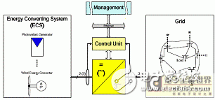
Figure 1 Inverter as a flexible multi-function basic connection between ECSs and the grid
1 inverter requirements for access to the gridToday, the inverters used by DERs and RESs still use passive control technology. This means that control of grid access power is closely related to energy conversion systems that generate electrical energy from primary sources. For the grid side, they are equivalent to a negative load. They inject all of the power obtained from the ECS into the grid. In this way, grid-side grid control integration, even active participation in control and stabilization of grid state variables is impossible.
The recent revision of the power system regulations has only provided a preventive response to abnormal grid changes. For high-voltage and medium-voltage networks, the UCTE operating manual, the national grid code, and the national grid connection regulations, the grid power connection behavior is defined. For low-voltage networks, the details of the procedures have not yet been defined and published. For high- and medium-voltage networks, steady-state requirements define that power generation units must reduce their active output to cope with excessive frequency or step-like output in accordance with grid scheduling requirements. According to this, the active power exceeding the demand will be rejected. Under normal operating conditions, the power generation unit must also provide reactive power. The definition of dynamic behavior requires that the power generation unit must remain connected to the grid in the event of a grid failure and be able to provide short-circuit current.
In order to increase the proportion of DERs and RESs in the grid, the rules and regulations should also undergo more in-depth changes. The distributed generation unit must undertake the same basic control tasks as the centralized power supply. Only in this way can the grid be operated by the motivator in a distributed form. Future power systems require not only DERs and RESs to assume assumed preventive measures and open-loop control. These power supplies must perform physical physical power system regulation. Only in this way can the centralized power supply be replaced or supplemented by DERs and RESs in the future.
2 Conventional power system control method in the inverter systemNew DERs and RESs must be involved in existing systems and adapt to existing structural and control strategies. The inverter must therefore adapt to the existing grid control and comply with the basic principles, especially in interconnected operation. Basic inverter control must be based on traditional power generation control methods and classified as shown in Figure 2.
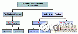
When the components connected to the grid are DERs or RESs, the conventional basic control mode can be adopted and executed by the inverter. The power transmitted to the grid can be driven by the ECS or the grid.
When the ECS drives the feed, the ECS determines the power delivered to the grid. Today, a single RESs inverter typically operates in this feed mode and injects all available power into the grid. When the grid drives the feed, it is no longer the ECS, but the grid determines the transmission of power. Typically, most conventional large power plants operate in this manner, and as such, this approach is potentially suitable for DERs and RESs systems, or at least for hybrid power systems. In the case of ECS drive feeds, the inverter control mode is referred to as the grid parallel mode. The second case can be implemented by two different inverter control methods, namely the grid formation mode and the grid support mode. The role of the inverter in the grid formation mode is to establish and maintain grid state variables. The inverter is used to balance the power in the grid support mode. It can transmit a preset amount of power, which can be adjusted according to the needs of the power system or the reference value obtained by the advanced control operation. An example of an inverter applying this control method is shown on the left side of FIGS. 3 to 5. In addition, the potential interconnection of these basic active power regulators to secondary grid control can be similarly explained.
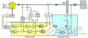
Figure 3 Grid control (GF) control method for inverters that are actively controlled and connected to the grid
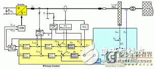
Figure 4 Grid control (GS) control method for inverters that are actively controlled and connected to the grid
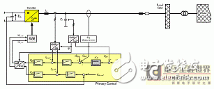
Figure 5: Grid control (GP) control of passively controlled inverters
All of the introduced control methods can accommodate both symmetrical and asymmetrical load conditions and inverter hardware. For these basic control methods, as described above, only the grid formation method and the grid support method are applicable to the entire power system that is actively applied to the physical level. The distributed generation unit cannot be controlled from the grid side in the grid parallel mode. However, in addition to adequate basic control, power generation unit control must be able to interact with the defined ultra-conventional secondary grid governor. This requirement can also be achieved by the basic control method described. Since these control structures are based on conventional power system control strategies, they provide the same secondary regulation interface as conventional power system control (as shown in Figure 5). Therefore, DERs and RESs with these functions can be connected to the grid control like a conventional unit. The secondary active governor in the grid is required to adjust the grid frequency to a normal value. It provides active power offset values ​​at the point of interest for grid formation and grid-supported control structures.
3 simulation researchSimulation is the first step in verifying the proposed control strategy, which uses a conventional power system control strategy. The test conditions are: two interconnected grids, each grid comprising a grid-forming inverter and a grid-supported inverter, as shown in Figure 6. The rated frequency and rated voltage of the grid are fred=50Hz and VLL=400Vrms.
The rated apparent power of the inverter in grid formation and grid support mode is Sr=125kVA and Sr=80kVA, respectively. The active and reactive power settings for both inverters are 6kW and 3.3kvar, respectively. The cable type used for the simulation is NAYY4 & TImes; 50SE, Rl = 0.772 Ω/km, and Xl = 0.083 Ω/km. In order to compare different inverter load distributions, the initial values ​​of the droop factors of all controllers are set the same. A secondary controller is used to control power switching and energy balance while maintaining normal frequency.
As shown in Figure 6, the initial conditions for active and reactive loads are the same for both grid settings, 16kW and 7.3kvar, respectively. This results in a system-wide power rating of 32 kW and 14.6 kvar, respectively. After 15s, add a step load to the grid 1. The active power is increased to 20.2 kW and the reactive power is increased to 7.37 kvar. Simulation results The active power, reactive power, frequency, three-phase voltage, and three-phase current are shown in Figure 7 to Figure 10.
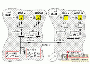
Figure 6 Two microgrids, each containing a grid-forming inverter and a grid-supported inverter
Figure 7 depicts the active power of the inverter. Initially, each grid-forming inverter provides 10 kW of power, and grid-supported inverters provide 6 kW of power. Thus, the two grid-forming inverters and the two grid-supported inverters share the load power equally. At 15 s, a 4.2 kW load step power is applied to the first grid. As the load changes, all inverters react immediately and power generation and consumption are redistributed.
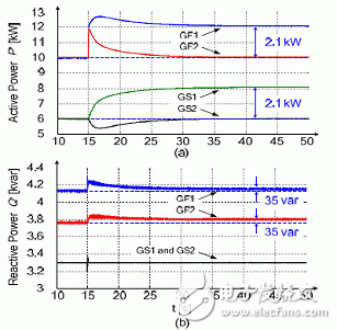
Figure 7 (a) Inverter active power (b) Inverter reactive power
After a period of time, the secondary controller controls the inverter action, and the step load on the first grid is only compensated by the inverter on the first grid. The exchange power is controlled back to the previous setpoint. The reactive power of different inverters is shown in Figure 7b. Initially, all inverters provided a reactive power of approximately 14.6 kvar. At 15 s, the reactive power of the first grid increased by 70 var. As mentioned earlier, this simulation does not have secondary control of reactive power. The grid-forming inverter compensates for the increased step load, and the grid-supported inverter provides the same amount of reactive power.
The frequency of the power system is shown in Figure 8. Since both primary and secondary control affect the grid frequency, but the impact is at different time scales, the response of the fast controller is shown in the amplification window.
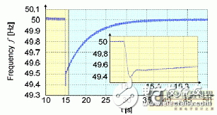
Figure 8 Power system frequency

Figure 9 (a) GF1 three-phase voltage with step load added at t=15s (b) GF1 three-phase current with step load added at t=15s
Since the 15s is added to the step load, the frequency drop is determined by the droop control function. When the frequency is quickly stabilized once, the secondary control is relatively slow to adjust the frequency back to 50 Hz.
The voltage and current at the junction of the inverter of the first grid formation mode are shown in Figure 9. The inverter voltage is almost undisturbed, while at the same time, only the current is adapted to the relevant load conditions.
Figure 10 illustrates the load voltage and current quality and control performance using the three-phase voltage and three-phase current of the first grid load as an example. At 15s, the load step is added to the grid. The load voltage remains almost constant, while the current increases with the step load.
Figure 10 (a) Load three-phase voltage with step load at t=15s
(b) Load three-phase current with step load at t=15s 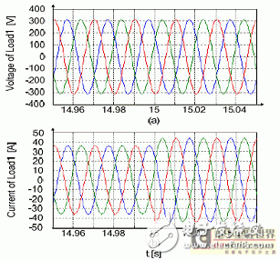
Verify that the second part of the standardized inverter control method described earlier is tested on a full hardware platform. Three modes of control structures are implemented under both symmetrical and asymmetrical conditions. Figure 11 shows the implementation of the inverter module in an isolated or interconnected operating state. Figure 12 shows a similar test case for asymmetric grid formation. Subject to the limitations of this paper, further test results will be published in subsequent papers.
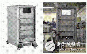
Figure 11 Inverter module platform and experimental test equipment
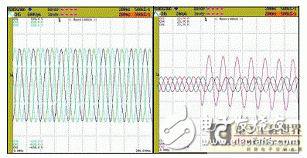
Figure 12 Asymmetric grid formation mode implementation: phase voltage and phase current measured under asymmetric resistance load step
At present, the power system is still based on the centralized control of high-voltage operation of conventional power plants. With the continuous access of passively controlled DERs and RESs, the ratio of controllable power will gradually decrease. The limitation of the excitation variables controlled by the power system can jeopardize the operational stability of the system. In order to achieve reliable control of the power system in the future, DERs and RESs must be authorized to actively participate in the regulation of the frequency and voltage of the grid state variables.
The new DERs and RESs are gradually being added to existing systems under the guidelines of detailed basic operating principles. In order to participate in this control system, existing conventional control strategies must be adjusted. The control strategy for grid-connected inverters must be based on standard conventional power plant feeds. According to the recommended strategy, DERs and RESs can actively participate in the physical control of the power system. Simulation studies have shown that when interconnected microgrids have only inverters based on recommended control methods, the grid can still operate. This control strategy has been successfully verified on the laboratory's inverter unit. The application of the recommended control strategy standard is only the first step towards establishing the liberalization of the conditions and energy supply of conventional power equipment for DERS and RESs at the physical and technical levels.
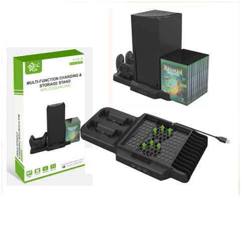
Xbox Series X Vertical Stand Cooling Fan
|
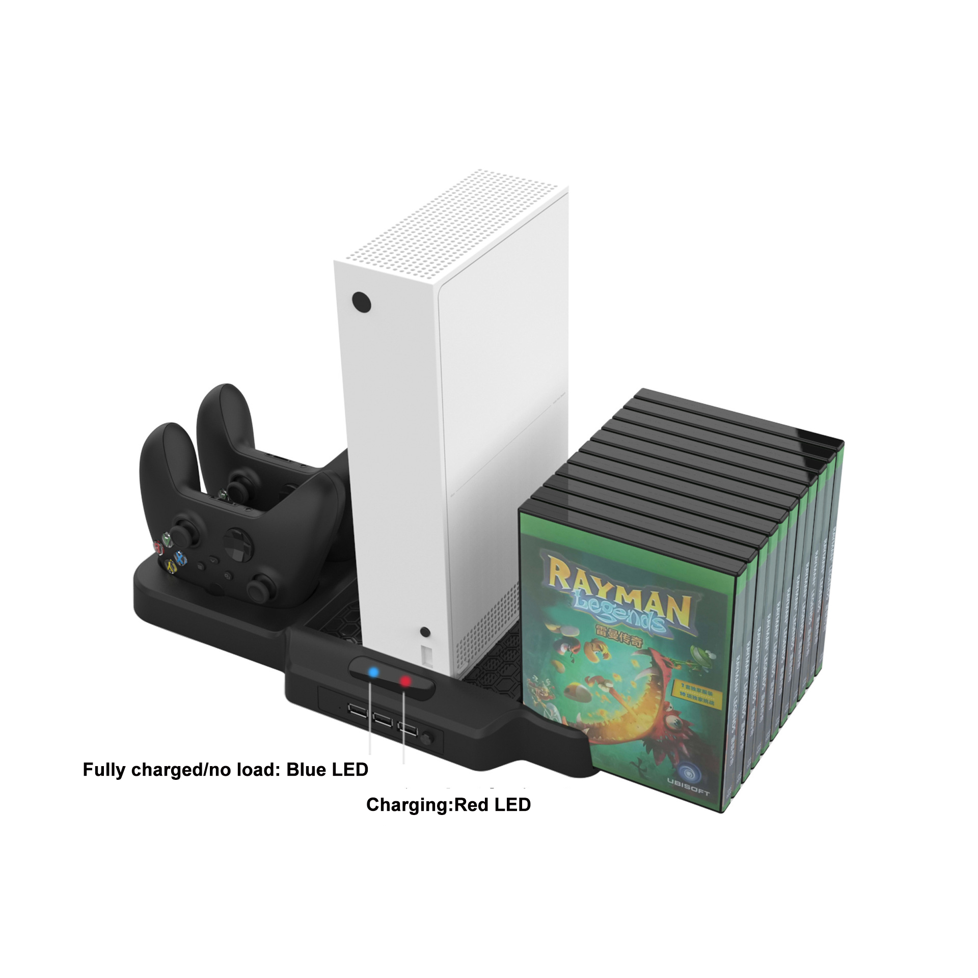
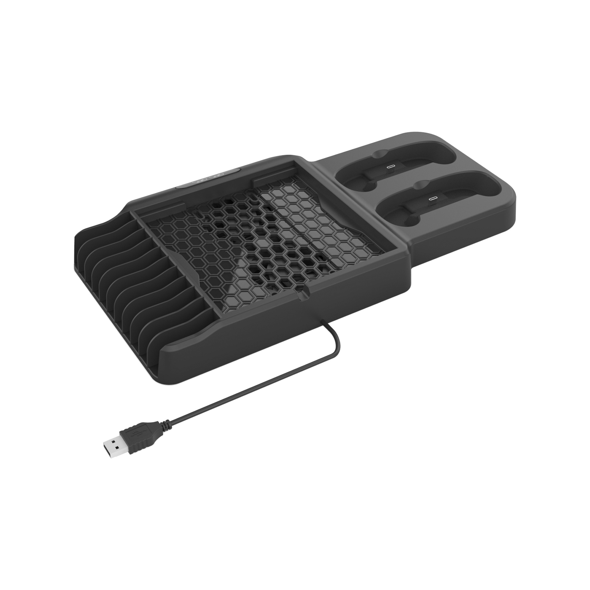
Design for X-box SX / SS game console and controller . Including 3 USB hubs,which can expand USB functions and easy to use
*Includes two charging docks, which can charge two X-box SX / SS controllers at the same time.
*With charging indicator function.When the indicator light is blue, it means it is fully charged or empty; if the indicator light is red, it means it is charging.
*Includes two cooling fans, 3000RPN, with a power button, which can quickly and effectively cool the x-box SX/SS game console. *The bracket can hold up to 11 game disc boxes. |
|
|
Product Name
|
Vertical Stand for Xbox Series X Game Console with 3USB BUB
|
|
weight
|
575g
|
|
Input
|
DC5V1A
|
|
Output
|
500mA
|
|
Product color
|
Black
|
|
Product size
|
20.5*4*36.3cm
|
|
OEM/ODM
|
warmly welcome
|
|
Advatage
|
100 QC test before shipping
|
|
Delivery Method
|
DHL,TNT,UPS , FEDEX ETC
|
Xbox Series X Vertical Stand Cooling Fan,Xbox Series X Vertical Stand,Xbox Series X Cooling Fan Station,X- Series X Cooling Fan
Shenzhen GEME electronics Co,.Ltd , https://www.gemesz.com