The vehicle tracking system is ideal for monitoring a car or an entire fleet. The tracking system consists of software that automatically tracks hardware and collects data (and, if needed, data transfers).
Today, we will analyze the "vehicle tracking system."
1. Active tracker and passive tracker
The active tracker and the passive tracker collect the data in the same way and are equally accurate. The main difference between these two types of trackers is time.
Active trackers are also known as "real-time" trackers because they send data over satellite or cellular networks to instantly indicate vehicle location. The computer screen can display the movement of the vehicle in real time. Therefore, if companies want to improve delivery efficiency and understand the on-site driving situation of employees, then active tracking is the best choice. The active tracker also has a "geo-fence" capability (thinking this function as a "force field") that provides a warning signal when the car enters or leaves a predetermined location. In addition, such systems can help prevent theft of vehicles or the recovery of stolen vehicles. Of course, active GPS tracking devices are more expensive than passive tracking devices and require monthly service fees.
Passive trackers are cheaper, but data storage is limited, but they are smaller and easier to hide. Passive trackers store information on the device instead of sending data to a remote location. This tracker must be taken off the vehicle and connected to the computer to view the information stored in it. This type of system is suitable for people who track miles for work purposes and for businesses that want to reduce vehicle abuse. In addition, passive trackers are often used to monitor the actions of people (imagine as detective work). Passive trackers are a good choice if you don't need immediate feedback, but check device data regularly.
No matter which type of tracker is, it is inherently portable and has a relatively small form factor. Therefore, battery power is required, and a backup function is required to save data in the event of a power outage. Since charging a battery (usually a single-cell Li-ion battery) requires a higher automotive system voltage and a larger current, a switch-mode charger is desirable because of the switching mode charger charging efficiency compared to a linear battery charging IC. Higher, less heat is generated in the form of power consumption. In general, the input voltage for embedded automotive applications can be as high as 30 V, and some even higher. In these GPS tracking and positioning systems, a charger and a common 12 V to single-cell Li-Ion battery (typically 3.7 V) for much higher input voltages (when voltage transients originating from battery drift occur) Additional protection and some type of backup capability will be an ideal configuration.
2, battery charging IC design issues
Traditional linear topology battery chargers are often valued for their compact footprint, simplicity, and modest cost. However, traditional linear chargers have some drawbacks, including limited input and battery voltage ranges, relatively large current consumption, excessive power consumption (heat generation), limited charge termination algorithms, and relatively low efficiency.
Switch-mode battery chargers are a popular choice because of their topological flexibility, which allows for the charging of multiple chemically-characterized batteries and high charging efficiency, thus minimizing heat and enabling fast charging. Has a wide operating voltage range.
Of course, the trade-offs always exist. Disadvantages of switching chargers include: relatively high cost, more complex inductor-based designs, possible noise generation, and large solution footprints. Due to the advantages of the above mentioned switching chargers, modern lead-acid batteries, wireless power supplies, energy harvesting, solar charging, remote sensors and embedded automotive applications are mostly powered by switch mode chargers.
Traditionally, the battery-oriented backup power management system in the tracker consists of multiple ICs, including a high-voltage buck regulator and a battery charger, as well as all discrete components, which is by no means a compact solution. Program. Therefore, the size of the early tracking system is not very compact. Typical tracking system applications use car batteries and single-cell Li-Ion batteries to support storage and backup.
Why does the tracking system require a more integrated power management solution?
It is necessary to reduce the size of the tracker itself. In this market, the smaller the size, the better;
Requires safe charging of the battery and protection against voltage transients for the IC, system backup capability to handle system power loss or failure, and relatively low power for the General Packet Radio Service (GPRS) chipset Rail voltage (~4.45 V) is supplied.
3, power backup manager
A solution that meets the aforementioned requirements and integrates a power backup manager and charger requires the following features:
Synchronous buck topology for high efficiency;
Wide input voltage range to suit a variety of input power sources, as well as protection against high voltage transients;
Appropriate battery charging voltage to support the GPRS chipset;
Simple and autonomous operation with built-in charge termination (no microprocessor required);
PowerPath? Control - Seamless switching between input and backup power in the event of a power failure. This control function also provides reverse isolation if an input short circuit occurs;
Provide a backup battery to power the system load when the input disappears or fails;
Due to space constraints, it is necessary to provide a flat solution with a small footprint;
Advanced packaging to improve thermal performance and space utilization.
To meet these specific needs, ADI introduced the LTC4091, a complete lithium-ion battery backup management system that is designed to maintain a 3.45 V to 4.45 V supply rail for long-term mains failure.
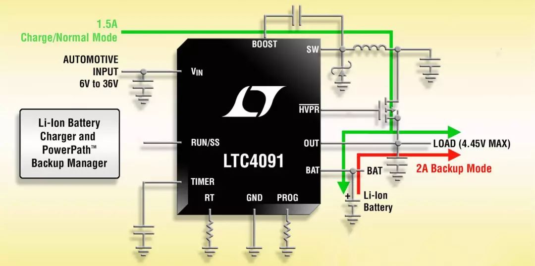
The LTC4091 features a 36 V monolithic buck converter with adaptive output control to supply the system load from the buck converter output and support high efficiency battery charging. When external power is available, the device delivers up to 2.5 A of total output current and can deliver up to 1.5 A of charge current for a single 4.1 V or 4.2 V Li-Ion battery. If the main input source fails and no longer supplies power to the load, the LTC4091 provides up to 4 A from the backup Li-Ion battery to the system output load through an internal ideal diode. If an external ideal diode transistor is used, it provides relative Restricted current. To protect sensitive downstream loads, the maximum output load voltage is limited to 4.45 V. In the event of a power failure, the device's PowerPath® control provides seamless switching between input and backup power supplies, and reverse isolation through short-circuit inputs. Typical applications for the LTC4091 include fleet and property tracking, automotive GPS data loggers and telematics systems, security systems, and communications and industrial backup systems.
The LTC4091 provides 60V absolute maximum input overvoltage protection, so the IC can withstand high input voltage transients. The LTC4091's battery charger provides two pin-selectable charging voltages optimized for Li-Ion battery backup applications: a standard 4.2 V voltage and a 4.1 V selectable voltage that can be weighed against battery run time and charge/discharge cycle life. Other features include soft start and frequency foldback to control output current during start-up and overload, as well as trickle charge, auto charge, low battery charge, charge timer termination, thermal regulation, and a thermistor for temperature qualified charging Pin.
The LTC4091 is available in a low profile (0.75 mm) 22-pin 3 mm x 6 mm DFN package with a back metal pad for superior thermal performance. The device operates over a temperature range of –40°C to 125°C. Figure 1 shows a typical application schematic for the device.
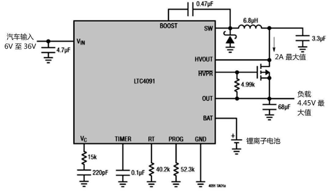
Figure 1 Typical application schematic of the LTC4091
4, heat regulation protection
To prevent excessive heat damage to the IC or surrounding components, if the die temperature rises to approximately 105 °C, the internal heat feedback loop automatically reduces the set charge current. Thermal regulation prevents the LTC4091 from overheating due to high power operation or high ambient temperatures, allowing users to break the limits of the power handling capabilities of a given board design without the risk of damaging the LTC4091 or external components. The benefit of the thermal regulation loop is that the charging current can be set to the actual conditions rather than the worst conditions, while ensuring that the battery charger automatically reduces the current under worst-case conditions.
5, through the car cold car launch situation
Automotive applications experience a significant drop in supply voltage. For example, in cold-start conditions, a large drop in supply voltage can cause the high-voltage switching regulator to lose regulation, resulting in excessive VC voltage and therefore excessive expansion when VIN is restored. Output overshoot. In order to prevent overshoot when recovering from cold start, it is necessary to reset the soft start circuit of the LTC4091 through the RUN/SS pin.
Figure 2 is an example of a simple circuit that automatically detects an undervoltage condition and resets the RUN/SS pin, reconnects the soft-start function circuit, and prevents damaging output overshoot.

Figure 2 Cold car launch crossing circuit
in conclusion
The adoption rate of car and fleet tracking systems is rising. Modern trackers are shrinking in size and capabilities, including active data transfer to support real-time tracking. In addition, backup functions and lower voltages to power the GPRS chipset in the system are required. ADI's Power by LinearTM product LTC4091 is a high voltage, high current step-down battery charger and PowerPath Backup Manager that provides thermal regulation and extensive protection, providing a compact, powerful and flexible single for vehicle tracking applications. The chip solution makes the designer's task easier and easier.
Big cloud vape kits for when you want the biggest clouds. All our vape mods ship from China.We are Disposable Vape supplier of big smoke.
Here're the best vape pen with big clouds in 2022.Best Vape disposable in the US.Best Vape Mods in the UK.
Big Smoke,Vape Big Smoke,Big Smoker Hqd,Smok Mesh Coil
Tsvape E-cigarette Supplier Wholesale/OEM/ODM , https://www.tsvaping.com