Programmable power supplies are power supplies where certain functions or parameters can be programmed and controlled by computer software. For example, what is the output voltage and how much the maximum output current is. Above this value, it cannot supply power normally. This article first introduces the function and working mode of programmable power supply, and then describes the application of programmable power supply in automotive electronics pulse testing and various types of test systems. Finally, the 12 factors of programmable power supply selection considerations are introduced. Follow Xiao Bian to find out.
The role of programmable power supply1, tracking function
In some programmable arbitrary power supplies, there is a function of linkage between channels, that is, tracking function. The tracking function means that all outputs are controlled at the same time, and that they are all subject to unified command by keeping the voltage consistent with the pre-set voltage. For example, if voltage 1 changes from 10V to 12V, then voltages 2 and 3 will change from 5V to 6V, and voltage 4 will change from 20V to 24V. However, if the output maximum current of one of the leading positions has a limit value and the output current reaches this limit, all the other subordinate output currents also enter the current limit state at the same time. If an electronic fuse is installed in the device, the output that reaches this limit value will be disconnected, and all other outputs in the slave position will also be disconnected.
2. Sensing (SENSE) mode - compensating the resistance of the wire itself
In normal mode, the voltage is directly applied to the load through the wire, which keeps the load voltage stable. Since the load current will cause a voltage drop across the connecting wire, the actual load voltage should equal the power supply output voltage minus this voltage drop. Vload = Vout - Vcable(1) Vcable = Iload × Rcable(2) In some applications where the output is low voltage, high current, the voltage drop across the output connection of the power supply cannot be ignored. If the power setting output is 3.3V/1A, assuming that the resistance of the output line is 0.3Ω, a voltage drop of 0.3V will be formed on the wire, then the actual voltage reached becomes 3.0V, which is enough to cause the power supply unit to fail normal work. Similar to the four-wire measurement method when measuring the resistance with a multimeter, we need to compensate for the wire voltage drop. To do this, use the SENSE terminal to directly measure the voltage across the load. Since the current in the SENSE conductor is very small, the resulting voltage drop is negligible, ie the voltage sensed by the power supply device is actually the actual load voltage, so that the power supply device will increase its own output to equal the conductor drop and required load. The sum of the voltages, so as to achieve compensation for the voltage drop of the wire, so that the load actually obtains the set voltage value. In addition, some power supplies incorporate readback to compensate for the resistance of the wire itself.
3, arbitrary waveform power
Some programmable arbitrary power supplies have an arbitrary waveform editing function, ie generate a time-varying waveform, such as the HM8143 from Huimei, Germany, which is equivalent to a fixed-point (eg, 1024-point) arbitrary waveform generator, ie The time interval parameter and list are generated correspondingly, and a user-definable waveform in the low frequency range can be generated. The frequency of this signal is determined by the time interval between each point. Any signal is generated in digital form and is fairly simple to define. In general, an arbitrary waveform signal may include various amplitudes of different sizes, and after processing one by one, a periodic repetitive waveform may be generated. These programming waveforms can be single pulses or repeated continuous waveforms. The programming output voltage can also be externally modulated. The signal can be freely defined within the allowable range of the instrument specifications and can be stored in the instrument. Such signals can be defined via RS-232, IEEE-488 or USB interfaces.
4, modulation
Some programmable power supplies have an external modulation function. Using the terminals on the rear panel, two sets of outputs can be modulated. For example, the German company HM8143, the modulation slope of up to 1V/μs and the minimum pulse width of 100μs in any mode allow the generation of complex load characteristics. Regardless of the power level, the distortion of the linear output components is very low to facilitate external modulation.
Programmable power supply operating modeThe operating modes of the power supply can be divided into a constant voltage output mode (CV), a constant current output mode (CC), a series mode, and a parallel mode. Among them, in the constant voltage mode, the output current of the power supply changes with the load to ensure the output voltage is constant. In the constant current mode, the output voltage of the power supply varies with the load to ensure the output current is constant. The output connection in parallel mode or in series mode must be performed independently, and the output of one power device can also be connected to the output of another power device. In order to obtain a larger output voltage, a series mode may be adopted, and in order to obtain a larger output current, a parallel mode may be adopted.
1) In series mode In series mode, since the voltages are added (or subtracted), the maximum current is determined by the power supply device with the smallest setting value, and the currents of all devices are equal at this time.
2) Parallel mode In order to increase the total output current, parallel mode can be adopted. The output voltage of all devices at this time is the same, and the size is determined by the power device with the lowest rated output voltage. The total current is the sum of the currents of the parallel branches. If the specifications of the power supply devices used are the same, check whether the currents distributed on each power supply device are even when connected in parallel. Since the currents flowing through the power supply devices are the same in parallel, if there are other types of power supply devices, there is no overload. Under protection conditions, such voltage may be damaged by the current.
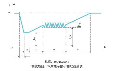
1, automotive electronics pulse test
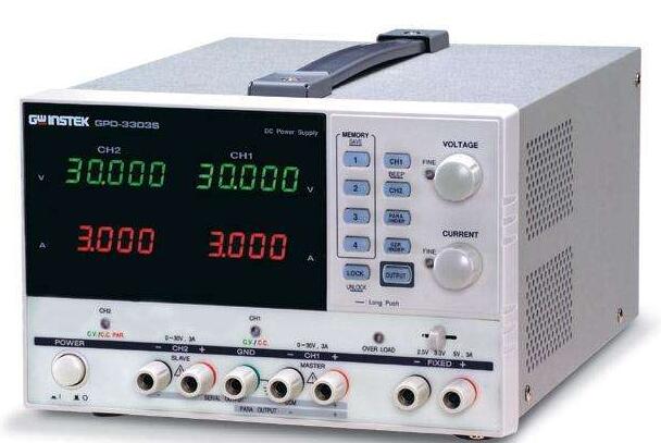
An internationally renowned brand automotive electronics product manufacturer uses this programmable power supply to perform voltage pulse test experiments on the product and use it to verify the reliability and stability of the product.
Using programmable DC power supply, built-in common test waveforms that meet the standards of the automotive electronics field, eliminating the need for cumbersome editing time before testing; test engineers can adjust the waveform parameters to output waveforms at different test levels;
The test waveform has strict requirements on the voltage rise and fall of the power supply, and the all-day programmable DC power supply has a national patent on this item, fully satisfying the test requirements;
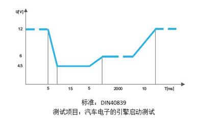
The test waveform is used to simulate the impact of the instantaneous voltage drop of other circuits on the electronic equipment after the fuse is broken in a complex automobile circuit;
The test waveform is similar to the test waveform under the DIN40839 standard. A test of the ripple component is added in the middle section, and a more realistic simulation engine startup test is performed.
2, all kinds of test systems
1) Sound Amplifier Test System
2) Bill Counter Main Control Board Test System
3) LED drive power function test system
4) Ballast, LED drive power aging system
5) Inverter control board and driver board test system
6) Welder control board, power board function test system
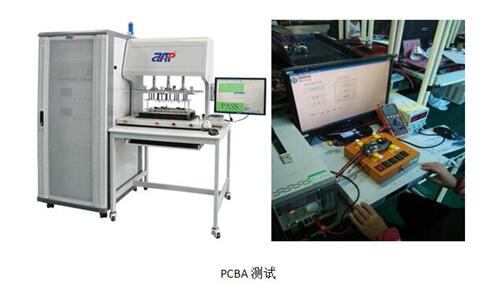
Using SP75VDC1500W model, through the fixture, with the operating software to test the electrical parameters between the PCB board points;
The customer used for production line test, needs to use 5V, 0.5A, 10.7V, 0.5A, 28V, 6A, 30V, 0.5A, 36V, 6A, 48V, 15A a total of 6 groups of outputs, requiring rapid switching to the required voltage Current, thus improving the production line efficiency and facilitating the use of the operator; In this regard, the full-day programmable power supply provides a quick call function, allowing the operator to achieve a set of desired voltages and currents with one key output;
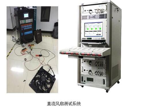
The SP32VDC1000W model is used for the DC fan test system; the all-day programmable DC power supply provides the DC fan to be tested in the system.
Programmable power supply selection considerations1, voltage, current, power demand range
Different voltages are often used to test the measured object (components, circuit boards, modules, and finished equipment). For example, the operating voltages of different circuit parts in the "1" circuit board may be different, and simulation work is required during testing. The environment provides different voltages; “2†also requires different voltages when performing undervoltage, normal voltage, and overvoltage tests on the measured object; “3†is often diversified in products that a company develops or manufactures. From the perspective of equipment investment, it is also expected that a power supply can satisfy as many application requirements as possible;
Different currents are often used to test the measured object (components, circuit boards, modules, and finished equipment). For example, "1" carries no load, 25% load, half load, and full load on the test object. In the overload test, different currents (powers) need to be provided; in “2â€, the products developed or manufactured by a company are often diversified. For example, chargers for R&D or manufacturing companies have different voltages and powers.
Even if the product is a single company, the OVP, OCP, and OPP tests are required.
In summary, the requirements for the voltage, current, and power of the power supply come out. Based on a comprehensive consideration of the budget and equipment investment returns, we can easily use one or several power supplies to meet our test requirements.
Many times, we often choose the combination of power supply to reduce our investment and meet our needs, such as: low voltage @ high current + high voltage @ low current + medium voltage @ high power
2, determine the string and parallel operation requirements

If a larger output current than a single power supply is required, we can implement multiple power supplies in parallel and master-slave control via the bus to ensure that the overall performance of the system complies with the parameter specifications for only one power supply; full-day master-slave control can be up to 10 units. , current sharing can reach within 0.3A;
When paralleling the power supply, use the same model for parallel connection; all the control is performed by the host power supply, and the total current is the sum of the current values ​​output from each power supply;
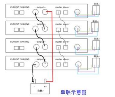
If you need a larger output voltage than a single power supply, you can use the DC power supply in series; (connecting the positive terminal of one power supply to the negative terminal of another power supply can connect multiple power supplies in series. The remaining positive and negative terminals are the same. Positive and negative poles of series connected power supplies ;)
All-day programmable DC power supply can be used for master-slave control in series operation. In the case of master-slave control, the set parameters can be output by setting the master. In this mode, the voltage will be uniform. All power supplies controlled by the master and slave will be controlled; for example, if 5 units are connected in series, in the master-slave control mode, if the output voltage is 50Vdc, the output voltage of each unit is 10Vdc; all the control is performed by the host, and the total voltage is not Can exceed 1000Vdc;
3, communication and control requirements
In application, many times, we need to integrate into the system and control it through the IPC. At this time, we need to communicate with the IPC. Then, you need to select the power supply with the communication interface. In a system, other devices also have communication. The requirements, and under normal circumstances, IPC communication interface will be diversified, which also need to integrate into the system of various devices can provide different communication interfaces can be selected; the communication interface of each device in the system, according to the IPC Coordinated with the device's communication interface to achieve a good effect of the operation, low investment in equipment; (All-day programmable DC power supply comes standard with four kinds of communication interfaces: RS232, RS485, LAN, USB, 2U models optional GPIB)
In some applications, analog quantities are needed for control. In this case, the power supply needs an analog control interface. Through such an interface, weak voltage, current, and resistance signals can be used to set and control the DC output voltage and current. ;
(All-day programmable DC power supply can provide WebServer remote control function at the same time, and can control DC output voltage and current through the computer using Web)
4, transient response
Transient response is an indicator of how well a power source reacts to current demand changes or changes in load impedance. For many applications, this is an important specification parameter; when the output current demand increases or decreases significantly in a short time, the output voltage may also significantly decrease or increase. The internal voltage control loop of the power supply will try to stabilize the output voltage at its set point, but this response is not instantaneous;
In order to improve the transient response speed, sometimes have to tolerate greater ripple and noise; in the programmable power supply, the internal voltage control loop and the output filter are mutually restricted; large output filter limits ripple and noise, However, reducing the power supply's response to rapidly changing loads. The ultra-fast internal voltage control loop reduces the transient response time, but may overshoot or undershoot, thereby damaging the test object.
Power tool test is a typical application of transient response. The application uses DC power to simulate the internal battery of the power tool; when the power tool motor starts, the current will increase sharply;
When testing relays and fuses used in cars, the situation is completely different. Programmable DC power supplies must supply large currents at voltages up to 30 VDC and typically require 5kW to 10kW of power. During the test, excessive DC output voltage overshoot can cause damage to the relay or fuse. To avoid this, the power supply used must be able to control the DC output current from zero to maximum instantaneously or from maximum to zero.
5, load regulation
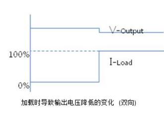
Another important parameter of the programmable power supply is the load regulation rate; it refers to the percentage of the output voltage that deviates from its set value due to the change of the current demand of the device under test; under normal circumstances, the effect of this effect should be small;
6, linear adjustment rate
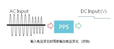
Line regulation ratio refers to the percentage change of DC output voltage or current caused by AC input line voltage change; this parameter is very important when the input line voltage is unstable;
7, slope
In general, the output voltage slope (rising and falling time) is also a parameter that needs to be considered; in order to improve the ripple and noise parameters, the output filter of the programmable DC power supply uses a large capacitor to store a large amount of energy; its charging and discharging time and measured The current demand of the object largely determines the voltage slope of the power supply.
The DC output fall time depends not only on the internal LCR filter network output from the programmable DC power supply, but also on the test requirements of the connected test object; if only through the current consumption of the measured object, especially the measured object When the power supply current capacity is relatively low, or when an empty test is performed, it may take several seconds for all the energy stored in the output capacitor to be “released†through the measured object; the all-day technology's programmable DC power supply achieves this. Patented, using a special circuit to dissipate energy, increase the slope parameter, and reduce test time;
In addition, one way to improve the slope is to select a programmable power supply with a higher DC output range; if the measured object is a power tool and only 20 Vdc power is required to meet all test application requirements, it is recommended to use a 40Vdc power supply, but the voltage limiting output only uses output voltages up to 20Vdc; this is because the 40Vdc power supply will require a much smaller output capacitance than the 20Vdc programmable power supply, resulting in two power supplies rising from 0V to The rise time required for 20Vdc or 40Vdc is the same; that is, from the rise time (unit: V/ms), the 40Vdc power supply will rise twice as fast.
8, loading performance
In some applications, the load-bearing performance of the power supply is also a major consideration. For example, for inductive and capacitive test objects, the input current absorbed by the test subject is very large (eg, air conditioning compressors). At the moment of starting, the motor starts instantly and the motor stalls. At this time, the current (power) of the power supply needs to be determined according to the characteristics of the measured object.
9, compensation function
This function is used to compensate line voltage drop; in all applications, there is a line voltage drop between the power supply DC output interface and the cable, and there is also a line voltage drop from the power supply DC output circuit to the power supply DC output to the external interface; When connecting the remote voltage compensation line of the power supply voltage to the connection position of the measured object, the voltage drop can be compensated to improve the test accuracy and accuracy;
10, constant current mode
Although most power supplies operate in constant voltage mode, there are many applications that require the use of DC power supplies in constant current mode. When operating in the constant current mode, the more important is the current control accuracy. It is not necessary to pay attention to the output voltage setting value accuracy and resolution, and the output voltage ripple and noise are not as important as output current ripple and noise.
1 1st, stable reliability
Stability is an indicator of the long-term drift of the output voltage or current of the power supply.
In the aging test of LED power supply, the programmable power supply is in a long-term running state. In this test, the power supply needs a stable and reliable operation for a long time; the stability is mainly expressed in parts per million or ppm.
12, budget
In the process of selecting the power supply, the budget is an important factor that must be considered. Consider the combination of the power supply products required by different parameters to reduce the investment. At the same time, the serial and parallel connections can be used to expand the capacity and increase the breadth of power supply coverage requirements.
Receptacle Wall Plate,Electrical Outlet Covers,Electrical Outlet Cover Plates,Wall Plates For Outlets
Lishui Trimone Electrical Technology Co., Ltd , https://www.3gracegfci.com