Today's laptops, including desktops, have gradually abandoned the parallel port and serial port. Many netizens have also told me that there is no parallel port on the desktop and the download line cannot be used. Let me help him think of a solution. It seems that being a USB-ISP download line is imperative.
Searched on the Internet, there are two main programs, one is to use FT245 serial chip plus ATMEGA8 program, the other is to use only ATMEGA8 USB serial port protocol software simulation and ISP download all completed. It is said that the first kind is stable, but the cost is high, the circuit is complicated, and it is inconvenient to make it. We are still following the principle of low cost and simplicity. Use a single M8 to do it.
it is good! Do not talk nonsense, work. Searching the Internet to find a BUG, ​​easy homemade map.
Before making the system, we must first make clear several points. First, the USB download line itself is an AVR microcontroller. After the system is completed, it must first download the program through other parallel or serial ISP download lines so that it can work. The second-come-first-hand overview of the basic information of this AVR stand-alone M8. Only in this way can the circuit have an understanding so as to facilitate debugging. Therefore, your original parallel ISP download line must play a key role here, but don't throw it away! I illustrated this process first:
Next, prepare the components as required by the above figure.
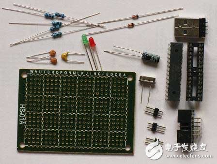
After the components are ready, the quality of the resistors, the resistance of the resistors, the polarity of the LEDs, and the capacitors are short-circuited. To test the regulator value of the next two regulators is correct. The most important thing is to first connect the USB interface to the PC with an extension cable, and then use a multimeter to measure where the positive pole is. Make a mark so that the position of the D+ and D- can be figured out and the power supply will not be connected. . After soldering, it is found that the polarity is repeatedly soldered repeatedly. The soldering pad is easily detached, and the components are also prevented from being reversed. (I started using the USB male interface. Later, I found that I couldn't eat on the board. I would probably loose it with a little effort. So I replaced it with my mother's mouth.)
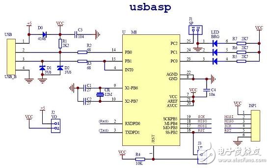
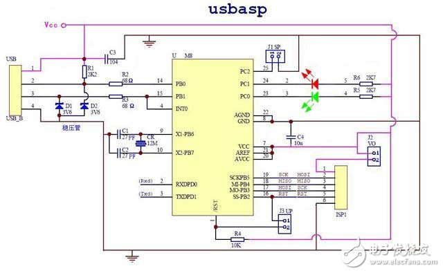
The circuit diagram I put together, because some of the components do not need, and some to facilitate the inspection, to avoid missing the line.
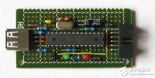
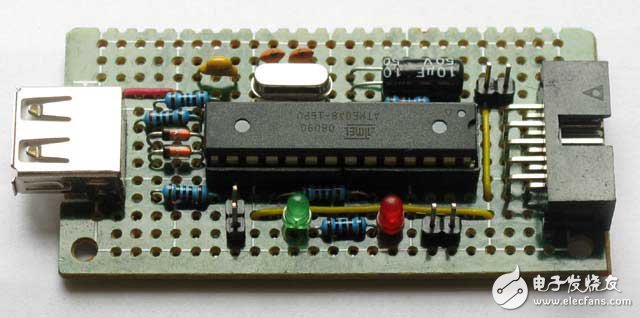
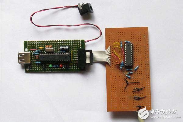
There is nothing to say in the welding process. It is not a PCB board. It is a hole board. It is probably a layout in advance (The layout principle is to reduce the length of the jumper. The jumper should be as small as possible. It seems that I do not have a lot of jumpers!) Then follow the above circuit diagram welding, after the completion of the following figure, I feel it is not bad? :
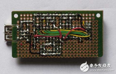
Let's face it again, a bit miserable!
Before debugging, you have to find out a few issues:
First, the power problem: The original parallel port download line is powered by the S51 board, which means that when you solder your USB-ISP board to install firmware, the USB-ISP board must supply power to the original parallel port download line. After the firmware is installed, the USB-ISP board is powered by the USB port of the PC to our USB-IS board, and you will not be able to supply power to the USB-ISP board. Otherwise, both the PC and the 51 experiment board will be powered. To supply power to the USB-ISP, it is possible to burn the PC's port or components with different voltages. Therefore, jumper J2 is used to distinguish between firmware loading and normal download. When the firmware is installed, a power supply is added to the USB-ISP, and J2 is short-circuited. The J2 port can supply power to the original parallel port download line. When in normal use, the additional power supply on the USB-ISP board is removed and powered by the USB port of the PC, which disconnects J2 and isolates the USB-ISP board and the 51-board power supply.
J1 is a speed-reduction jumper. When it is shorted, it is slow. When loading firmware, slow speed is required. J3 is the M8 reset jumper, which requires M8 to be reset during firmware installation. Disconnect these three jumpers during normal use.
Second, the ISP interface problem: you have to find out the corresponding interface to download the interface, MOSI, MISO, RST, SCK should be one-to-one correspondence can not be mistaken. In other words, the function line of the parallel port of your original parallel port download line is connected to the ten pin ISP interface and the USB-ISP download line interface. For example, my 51-board is made by myself. The above ten-pin download interface is free to meet my own criteria. So when I do a parallel port download line, I will connect each function line of the parallel port download line to the one on the 51 board, so that I can debug it. Now that the USB-ISP download line is still the same, I have to follow my own ten-pin interface, as long as each function line is correct.
J1 is a speed-reduction jumper. When it is shorted, it is slow. When loading firmware, slow speed is required. J3 is the M8 reset jumper, which requires M8 to be reset during firmware installation. Disconnect these three jumpers during normal use.
The definition of the different PC-side download software is different from the definition of the user's mouth. This must be made clear, otherwise it is impossible to download normally. Some software has a configuration file that can be set according to your requirements. Such as ISPLAY 1.5. Its configuration file is shown in Figure:
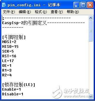
You can modify the output of these MOSI, MISO, SCK, RST, OE, LE and other parallel ports to adapt to your download line.
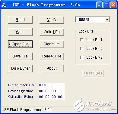
My original parallel download line used an official map:
Its supporting PC-side download software ISP-30A can not set the parallel port pin number. The interface is as shown below.
it is good! Start debugging and check that the USB-ISP download board is not connected to the wrong line or a short circuit. Short the three jumpers of the USB-ISP download board, connect the external power supply, and measure the current to 6mA. It should be no problem. Connect the parallel port of the original parallel port download line to the PC, connect the ten-pin ISP port to the USB download board, and measure that the voltage on the parallel port board is normal. As shown below: (I'm a schematic diagram, because the PC is not well-lit in the house and it's not clear)
At this point, the LED on the USB download board will not light because there is no program in it and it cannot run. Start the download. Running ISPLAY1.5 on the PC as shown in the figure:
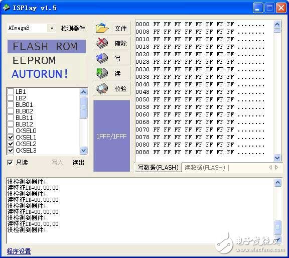
In advance, I changed the function lines in the configuration file Pin_config.ini to the same pin numbers as my parallel download line. Select the configuration file in the "Program Settings" in the lower left corner. Click the Detect Device button, but no device is detected at all times, as shown above. I think my parallel download line is definitely good and has been used! Is the configuration file not working? Or is that LE control timing different from my board requirements? Just try it with the ISP-30A that I have been using! So run it. Because you want to download the program for ATMEGA8, select MEGA8 in the device options.
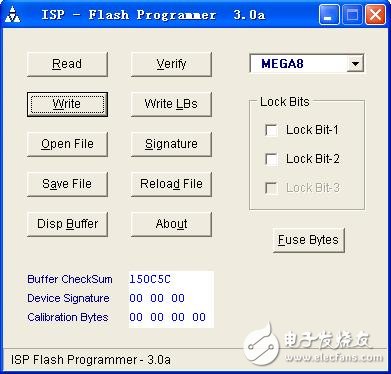
Sure enough, I click Read, and I can read it normally. So I click Open file and select the 11K main.hex on the Internet. Click Write to write the program and verify everything OK. Then click on Fuse Bytes and click on the SUT0 and CKSEL0 points in the figure below.
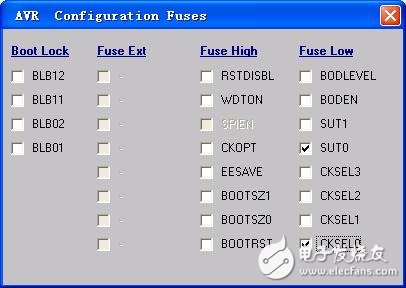
Then return to the main interface point Write LBs. When I finished writing, I pulled three jumpers and the green LED was on, indicating that the M8 program was running. In this way, the firmware of my USB download board is installed.
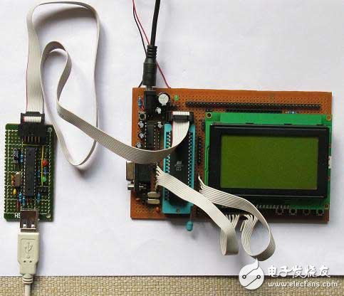
Unplug the USB download board from the parallel port downloader. I removed the additional power and plugged it into the USB port of the PC. I found the new USB device immediately. Everything was not suspicious. I installed the driver all the way. It has been written in great detail. I will not repeat it.) The PC told me that the device is ready for use. I connect my 51 board and USB download cable
Run PROGISP 1.6.6
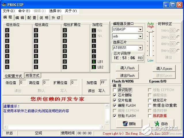
After a period of ecstasy, I selected USBASP in the box under "Programmer and Interface" and chose AT89S51 in "Select Chip".
Click the RD button to the right of "Chip ID", oh! Can not detect the device as shown below:
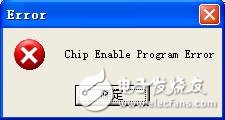
This window pops up, indicating that the USB cable is normal, that is, it cannot detect 51 target boards. Is it ISP connection too long? I also made a root ISP connection with only 10CM, but the situation remains the same.
Suddenly remembering the online use of the modified firmware for the 51 Enable Chip Program Error. Immediately on the Internet to find the 18K size USBISP.hex, redo the download work just now, everything went well, and then run PROGISP1.6.6
Haha! 51 devices detected,
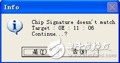
Feature words do not match, regardless of it, first click "Yes". So try to click the "Read Flash" button. success!
I then click on "Load Flash" to select one of my previous HEX files. Click on the Auto button below. The red LED flashes and I am happy!
However, after finishing the check, it always fails, Khan!
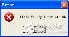
Is the download line too long and unstable? 10CM is left, don't you really pity me? In a burst of helpless random operation, try to choose AT89S52.
This test does not matter! Actually successful! Repeatedly downloading different programs, everything is OK.
Then put my long 40CM ISP connection, repeatedly download the program test, guess what? Don't be too stable!
You're done!
to sum up:
When downloading the firmware, if your original parallel port download software supports ATMEGA8. It is best to use the parallel port you have been using to download the software. In this way, you can first eliminate the issue of the parallel download line.
Try to try several more problems and don't give up easily.
Is there a bug in this PROGISP1.66? Obviously S51, it is only necessary to select S52 to read and write normally. There is also ISPLAY 1.5, it is estimated that the configuration file does not work is that the LE's timing and my parallel download online requirements are not the same. Then find time to find the reason.
I wrote about the installation of the driver and the download later. This is because the software has been written on the Internet very thinly. I can search for it by searching "USB-ISP" on the Internet.
E-glass rod,Power fittings,Insulator fittings,Polymer insulator
TAIZHOU HUADONG INSULATED MATERIAL CO.,LTD , https://www.thim-insulator.com