Introduction:
The MC9S12G series is an optimized automotive-grade 16-bit microcontroller product line with the notable features of low cost, high performance, and a small number of pins. The MC9S12G series is suitable for general automotive applications requiring CAN or LIN/SAE J2602 communication.
Basic characteristics:
The MC9S12G series has all the advantages and efficiencies of 16-bit MCUs, while retaining the low cost, low power consumption, electromagnetic compatibility (EMC) and code efficiency advantages that Freescale's existing 8-bit and 16-bit MCU series users enjoy.
MC9S12G128/96 and MC9S12GN32/16 are the first four main products launched by MC9S12G series on the market.
Features include:
S12 CPU core, 25MHz bus
Up to 240 KB on-chip flash memory with error correction code (ECC),
Up to 4 KB EEPROM with error correction code (ECC),
Up to 11 KB on-chip SRAM
A multi-layer expansion controller local area network (MSCAN) module (supports CAN protocol 2.0A/B)
Three serial communication interface (SCI) modules to support LIN communication, and three serial peripheral interface (SPI) modules
Precision fixed voltage reference for ADC conversion
1 MHz internal oscillator
On-chip voltage regulator regulates input power and all internal voltages
Program features:
The MC9S12G128 Controller Board is designed to a drive 3-phase BLDC motor, enabling implementaTIon of motor control techniques:
• Sensorless:
— Back-EMF signal sensing using an MCU ADC module
— Back-EMF zero-cross signal monitoring
• Sensor based:
— Hall sensor signal monitoring
On-board UNI-3 interface enables control of the BLDC motor power stage.
The LIN and CAN communicaTIon interfaces connect the board to the other automoTIve network nodes.
The USB interface is targeted at FreeMASTER PC-based applicaTIon control.
The MC9S12G128 Controller Board features follows:
• MC9S12G128 microcontroller, 100 LQFP package
• BDM interface for MCU code download and debugging
• MC33905 System-basis chip (power supply, connectivity)
• Motor control interface:
— UNI-3
— MC33937A predriver
— Hall sensors
• Connectivity interface:
— LIN (MC33905)
— CAN (MC33905)
— USB interface
• LEDs:
— Power-on indicators
— Phase A, B, C PWM control signals
— Phase A, B, C zero-cross
— Hall sensor outputs
— Fault monitoring
— SBC safe mode
— User application
• Rotary encoder switch for an application control
• On-board PWM dead time generation
• MCU pins accessible via pin headers
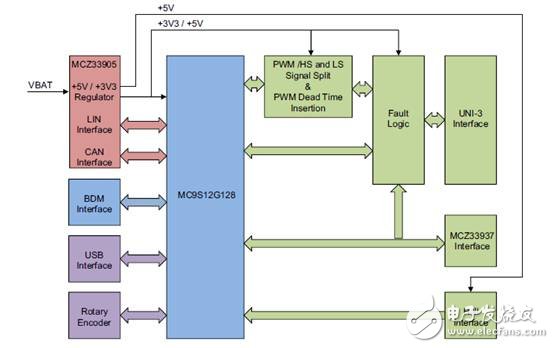
Figure 1 Reference block diagram
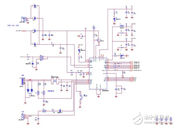
Figure 2 Reference Schematic 1
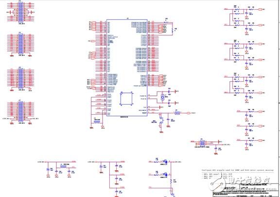
Figure 3: Reference Schematic 2
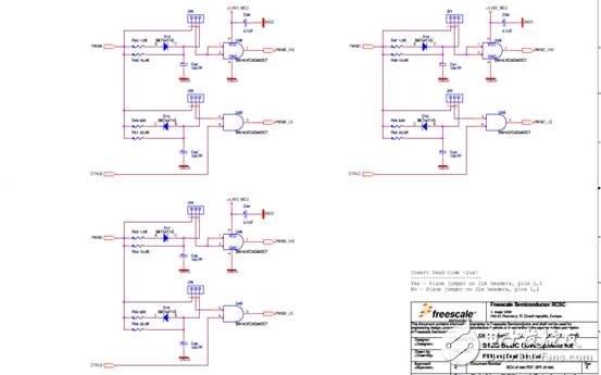
Figure 4: Reference Schematic 3
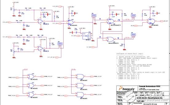
Figure 5 Reference Schematic 4
LED DJ Display
LED DJ Booth is used different product models and structures as different conditions, which can be customized to the scene modeling. It can be spliced out the unique shape with different sizes of triangles, rectangles, hexagon. Unique DJ Table is not limited to kinds of environment. The application of the relevance and the shape of DJ LED Video Wall can enhance scene recognition.
LED Bar Display will not only present a delicate and realistic color performance through the synchronization adjustment, but also is compatible with different sources of input such as TVV, HDV, DVI, VGA, SDI. We adopt SMD technology to achieve super-wide viewing angle and better surface smoothness. Super light cabinet is to realize easy installation and maintenance that can be customized for shapes, sizes, pixels, resolution.
LED DJ Display, LED DJ Booth, DJ LED Video Wall, LED Bar Display
Shenzhen Priva Tech Co., Ltd. , https://www.privaled.com