1. Reason for disqualification
For the test equipment immunity, the electric fast pulse test is of typical significance. Because the rising edge of the waveform of the electric fast pulse test is very steep, it contains a very rich high-frequency harmonic component and can test the circuit at a wider frequency. In-range immunity. In addition, because the test pulse is a pulse train that lasts for a period of time, it has a cumulative effect on the interference of the circuit. Most circuits are equipped with an integrator circuit at the input to resist transient interference. This circuit has good effect on a single pulse. The inhibitory effect, but for a string of pulses can not be effectively suppressed.
The reasons for the impact of the electric rapid pulse on the equipment are shown in the figure below.
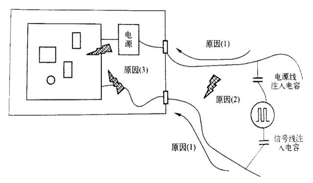
(1) Power is directly conducted into the device through the power line, causing excessive noise voltage on the power line of the circuit. It can be seen from the interference injection method shown in the figure that when the interference to the live wire or the neutral wire is separately injected, there is differential mode interference between the live wire and the neutral wire. This differential mode voltage will appear at the DC output of the power supply; In the case of interference with the live and neutral lines, there is only a common-mode voltage. Since most of the power supply inputs are balanced (whether the transformer input or the rectifier bridge input), the actual common mode interference is converted into a differential mode voltage component. Less, there is little impact on the output of the power supply.
(2) Interference energy is radiated into the space during the conduction process on the power line. These energies are induced on the adjacent signal cable and interfere with the circuit connected to the signal cable. If this happens, the signal cable is often directly injected into the test. In the event of a pulse, the test failed.
(3) The secondary radiant energy generated when the interference pulse signal propagates on the cable (including the signal cable and the power cable) is induced into the circuit and interferes with the circuit.
2. Corrective measures
1) Measures against the power cord
(1) Metal chassis. The main method to solve the power line interference problem is to install a power line filter at the entrance of the power line to prevent interference from entering the device. From the disturbance injection method shown in the figure, the voltage injected into the power line is a common-mode voltage, and the filter must be able to suppress this common-mode voltage in order for the EUT to successfully pass the test. At present, many finished power supply filters on the market are mainly designed for electrical fast pulse tests, and designers can directly select them according to the product features. The following is a method of using the filter to suppress the electric fast pulse on the power line.
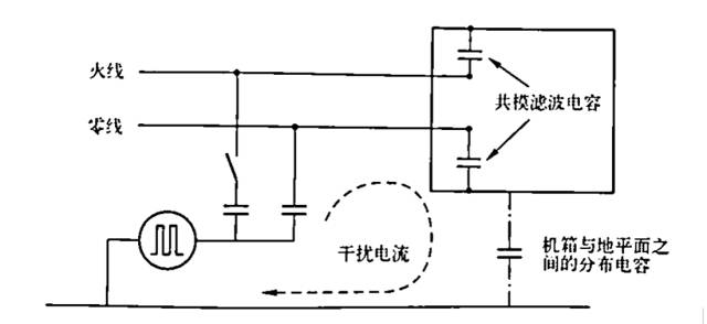
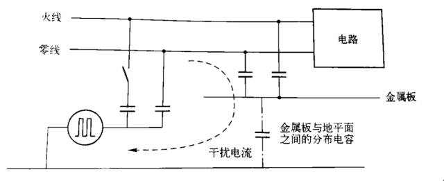
(2) The equipment chassis is non-metallic. If the equipment uses a non-metal chassis, a metal plate must be added to the bottom of the chassis to ground the common-mode filter capacitors in the filter. As shown in the figure, the common-mode interference current path forms a path through the distributed capacitance between the metal plate and the ground layer. If the size of the device is small, it means that the size of the metal plate is also small. At this time, the capacitance between the metal plate and the ground layer is small, and it cannot play a good bypass role. Therefore, the characteristics of the inductor are critical for the device to pass the test. It is necessary to adopt various measures to improve the high-frequency characteristics of the inductor. If necessary, multiple inductors can be connected in series.
2) Measures for signal lines
(1) Signal cable shielding. From the test method, it can be seen that the way in which the interference pulse is coupled into the signal cable is capacitive coupling. The method to eliminate the capacitive coupling is to shield the cable and ground it. Therefore, the reverse method of cable shield to solve the problem of electrical fast pulse interference is that the cable shield can be reliably connected with the ground reference layer under test if the device housing Metal and grounding equipment, this condition is easy to meet; when the device's shell is metal, but not grounded, the shielded cable can only inhibit the high-frequency components in the electric fast pulse, this is through the metal chassis and The distributed capacitance between grounds is grounded; if the chassis is a non-metal chassis, the method of cable shielding has no effect.
(2) Install a common mode choke on the signal cable. The common mode choke is actually a kind of low-pass filter. According to the suppression effect of the low-pass filter on the pulse interference, the effect can only be achieved when the inductance is large enough. However, when the inductance of the choke coil is large (in many cases, the number of turns), the distributed capacitance is also large, and the high-frequency suppression effect of the choke coil is reduced. The electric fast pulse waveform contains a large number of high frequency components. Therefore, in actual use, it is necessary to pay attention to adjusting the number of turns of the choke coil, if necessary, using two choke coils of different number of turns in series, taking into account the requirements of high frequency and low frequency.
(3) Twisted pair cable is used as the signal cable of the equipment, and a ferrite magnetic ring is added at the interface of the equipment signal line (that is, near the end of the equipment), and the signal line is wound on the magnetic ring for 2 to 3 turns for resistance. The effect of this measure is not bad for devices whose interference capacity is not too weak.
(4) Install common-mode filter capacitors on the signal cable. This filter method has a better effect than a choke coil, but it requires a metal chassis as ground for a filter capacitor. In addition, this method will have a certain attenuation of the differential mode signal, and attention should be paid when using it.
(5) Partial shielding of sensitive circuits. When the equipment chassis is a non-metal chassis, or the shielding and filtering measures of the cable are not easy to implement, the interference will be directly coupled into the circuit. At this time, the sensitive circuit can only be partially shielded, and the shield body should be a complete hexahedron.
Bluetooth Mini Projector
Sound can be transmitted wirelessly, no audio source cable is required.
1. The Bluetooth function of the projector can be connected to a Bluetooth speaker, and you can enjoy better sound quality when watching movies and playing music;2. After the projector is connected to the mobile phone through the Bluetooth function, the projector acts as a speaker and can play music from the mobile phone.
wifi bluetooth projector,bluetooth home projector,bluetooth protable home projector
Shenzhen Happybate Trading Co.,LTD , https://www.szhappybateprojectors.com