1. Background
For a recent project, I need to use STM32. It is the same point of view as before. The clock is the heart of the MCU, and the blood supply is the output of the clock frequency. If you want to understand an MCU, the clock is a very good entry point. Closer to home, there have been too many masters on the Internet that have detailed the detailed configuration method of STM32. Here is a brief introduction to the STM32 clock system and how to configure it as a simple record to facilitate rapid development in the future.
Second, the text
Not much nonsense, the previous clock tree diagram of STM32F10xx:
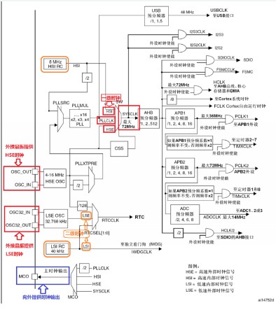
As can be seen from the figure, STM32F10XX has two levels of clock
First-level clock
* High-speed internal clock (HSI)
* Phase-locked loop clock (PLLCLK)
* High-speed external clock (HSE)
Secondary clock
* Low-speed internal clock (LSI)
* Low-speed external clock (LSE)
It can be seen from the figure,
* HSE is provided by external crystal oscillator from "OSC_OUT" and "OSC_IN" two-pin input.
* LSE is provided by external crystal oscillator from "OSC32_OUT" and "OSC32_IN" two-pin input.
* HSI is provided by 8MHZ high-speed internal RC oscillation circuit.
* LSI is provided by 40kHZ low-speed internal RC oscillation circuit.
STM32F10XX can also provide clock output through the MCO pin. The clock source is PLLCLK/HSI/HSE/SYSCLK, which is selected by the MCO selector.
After studying the source of the clock, let's study the whereabouts of the clock. For the MCU itself to function normally, it needs a clock. This clock is the system clock (SYSCLK), and basically all peripheral clocks come from this system clock (SYSCLk). Then the system clock provides various peripheral clocks to the outside. See the picture for details.
Of course, there are exceptions. The USB clock must be 48MHZ. Here, the USB clock (USBCLK) is directly provided by PLLCLK, and the RTC clock (RTCCLK) is not derived from the system clock (SYSCLK), as shown in the figure.
The clock structure is basically the same, no longer go into details, there are many more in-depth explanations on the Internet, and then I will talk about how to configure it. Use code to illustrate the problem:
First paste the file "system_stm32f10x.c", this file is the library file. There is a very important function "SystemInit()"
Friends who have analyzed the STM32 startup code should know that this function runs before entering the main function, and what it does inside is to configure the system clock. code show as below:
voidSystemInit(void){/*ResettheRCCclockconfigurationtothedefaultresetstate(fordebugpurpose)*//*SetHSIONbit
Laser cutting provides greater precision in stator and rotor machining, using a highly focused beam that acts as a heat-affected zone during cutting without causing extensive thermal damage to adjacent surfaces. The finishing is cleaner, smoothing the edges of complex shapes and designs. Laser cutting machine with computer numerical control function, laser cutting process can be automatically controlled by the pre-designed machine program. CNC controlled laser cutting machines reduce the risk of operator error and produce more precise, precise parts with tighter tolerances.
The use of laser cutting method can reduce the total lead time, the total cost of production. For laser cutting, it can be processed by drawing, without making molds, and without mold replacement and setting between materials or material thickness. Compared with traditional cutting methods, laser cutting setup times can be greatly reduced and it involves more machine programming than loading materials.
Lower material cost
Our current production technology supports laser cutting for stator and rotor production.
Stator And Rotor Lamination With Laser Cutting
Henan Yongrong Power Co., Ltd , https://www.hnyongrongglobal.com