With the adjustment of the electronic technology industry structure, the rapid development of production technology, the continuous improvement of people's living standards, the gradual popularity of household appliances, and the market demand for intelligent clock control systems is increasing. The intelligent clock control system mentioned in this article mainly refers to the control system such as clock display, time setting, alarm and timing switch of household appliances (expandable function).
This article adopts MCS-51 single-chip microcomputer with early market entry time, open bus, many simulation development equipment, low price of chips and development equipment, high speed, and good electromagnetic compatibility as the core to realize intelligent clock control.
Hardware system design
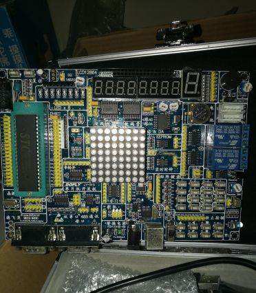
The intelligent clock control system takes MCS-51 compatible single-chip AT89C51 microprocessor as the core, and is composed of clock display module, timing control module, power supply module and other circuits.
AT89C51 microprocessor
AT89C51 is a single-chip microcomputer that is manufactured using ATMEL high-density non-volatile memory manufacturing technology and is compatible with the industry standard MCS-51 instruction set and output pins. Its main performance characteristics are:
(1) High-performance, low-power 8Byte microcontroller, RISC simplified instruction set mechanism, powerful instruction functions, and most of them are single-cycle instructions, with low-power idle and power-down control modes, 5 interrupt sources, two A 16-bit timer/counter and other functions.
(2) The chip integrates 4KB programmable flash memory, which can perform more than 1000 write/erase cycles, the data retention time can reach 10 years, and it supports three-level program memory lock.
(3) Rich and powerful external interface performance: 32 programmable I/O lines, programmable serial channels, on-chip oscillators and clock circuits.
Clock display module
The display module uses LG2841BH digital tube, dynamic scanning, 8550 transistor position selection drive, AT89C51 microprocessor P0 port direct segment selection to realize hour and minute display, with strong display brightness, good stability, and less display error.
Timing control module
This module cooperates with the corresponding program to realize functions such as time adjustment, alarm, and time switch of household appliances. P3.2 is the time adjustment mode selection key, P3.3 is the hour adjustment key, and P3.5 is the minute adjustment key; the timing control realizes the control function through the relay JZC-32F and JRC-Z7F, and the timing control function can be performed by modifying the program Expansion to realize functions such as time switch of household appliances.
Power module
The quality of the power module design is directly related to the stability of the single-chip microcomputer system. In the design system, since the single-chip microcomputer, control relay and other components can be powered by DC +5V, the three-terminal voltage regulator integrated circuit LM7805 with better voltage regulation performance can be used for realization.
Software system design
The system uses Weifu 6000 to write source code and MEP500 to program AT89C51 chip to realize the intelligent clock control function. Because the system software mainly completes functions such as clock display, alarm, and time setting. The source program mainly includes the main program, interrupt subroutine, display subroutine, timing subroutine, delay subroutine, etc.
The implementation procedure is as follows:
...
;**************************; The following is the main program (check whether each key is pressed)
;***************************MainLoop:
jb AlarmSetKey, CheckMinuteKey
call Delay
jb AlarmSetKey, CheckMinuteKey
setb ClockMode
call AlarmSet
CheckMinuteKey:
jb MinuteKey, CheckHourKey
mov a, Minute
add a, #1
mov Minute, a
cjne a, #3ch, NotOver1
mov Minute, #0
NotOver1:
jnb MinuteKey, $
CheckHourKey:
jb HourKey, CheckAlarmA
mov a, Hour
add a, #1
mov Hour, a
cjne a, #18h, NotOver2
mov Hour, #0
NotOver2:
jnb HourKey, $
CheckAlarmA:
jnb AlarmTimeOnA, CheckAlarmP
call StartPc; call AlarmProcess
ajmp ToReturn
CheckAlarmP:
jnb AlarmTImeOnP, ToReturn
call ShutPc
ToReturn:
ajmp MainLoop
;**************************; Timer TImer0 interrupt service program (this program is executed every 8ms)
;***************************
TImeInt:
mov th0, #0E0h
mov tl0, #0bfh
push acc
push psw
SETB rs0
clr rs1
d jnz OneSecondCounter, NotoneSecond
mov OneSecondCounter, #125
call Clock
call ConvertoBuffer
NotoneSecond:
call ScanDisplay
pop psw
pop acc
reTI
; ***************************
; Scan display subroutine
;***************************
ScanDisplay:
mov r1, #DisplayBuffer
mov R4, #11111011b
play:
mov a, R4
mov P2, A
mov A, @R1
mov DPTR, #TAB
movc A, @A+DPTR
mov P0, A
lcall Delay
inc R1
mov A, R4
jnb ACC.7, ENDOUT
rl A
mov R4, A
ajmp PLAY
endout: SETB P2.7
mov P0, #0FFH ret
TAB: DB 0C0H, 0F9H, 0A4H, 0B0H,
99H, 92H, 82H, 0F8H, 80H, 90H, 7FH,
0B7H, 0FFH
;***************************
; Subroutine to add 1 second to the contents of the clock
;***************************
Clock:
mov a, Second
add a, #1
mov Second, a
cjne a, #3cH, NotOverFlow
mov Second, #0
mov a, Minute
add a, #1
mov Minute, a
cjne a, #3cH, NotOverFlow
mov Minute, #0
mov a, Hour
add a, #1
mov Hour, a
cjne a, #18H, NotOverFlow
mov Hour, #0
NotOverFlow:
mov a, Second
jnz NotAlarm
jnb AlarmAOnOff, PAlarm
mov a, Minute
cjne a, AlarmAMinute, PAlarm
mov a, Hour
cjne a, AlarmPHour, PAlarm
ajmp alarming
PAlarm:
jnb AlarmPOnOff, NotAlarm
mov a, Minute
cjne a, AlarmPMinute, NotAlarm
mov a, Hour
cjne a, AlarmPHour, NotAlarm
ajmp Alarming1
Alarming:
setb AlarmTimeOnA
ajmp NotAlarm
Alarming1:
setb AlarmTimeOnP;
NotAlarm:
ret
;***************************
; Convert clock content or alarm time setting value to display buffer subroutine
;***************************
ConvertoBuffer:
mov r1, #DisplayBuffer
jb ClockMode, DispAlarmSet
mov a, Second
mov DispSecond, a
mov a, Minute
mov Dispminute, a
mov a, Hour
mov DispHour, a
ajmp Convert
DispAlarmSet:
jb AlarmAOnOff, AlarmAOn
mov DispSecond, #00h
jb AlarmPOnOff, AlarmPOn
mov DispSecond, #00h
ajmp Convert
AlarmAOn:
mov DispSecond, #11
NextA:
mov a, AlarmAMinute
mov Dispminute, a
mov a, AlarmAHour
mov DispHour, a
ajmp Convert
AlarmPOn:
mov DispSecond, #11
NextP:
mov a, AlarmPMinute
mov Dispminute, a
mov a, AlarmPHour
mov DispHour, a
Convert:
mov a, DispSecond
mov b, #10
div ab
mov @r1, b
inc r1
mov @r1, a
inc r1
mov a, DispMinute
mov b, #10
div ab
mov @r1, b
inc r1
mov @r1, a
inc r1
mov a, DispHour
mov b, #10
div ab
mov @r1, b
inc r1
mov @r1, a
ret
Concluding remarks
The intelligent clock control system, with AT89C51 microprocessor as the core, has the advantages of high integration, stable performance, strong anti-interference ability and high cost performance. The software simulation and actual function verification prove that the design is reliable, the design scheme is feasible, and has greater practical value in practical applications.
60V Battery Pack ,Battery Pack With Outlet,Back Up Battery Pack,Ev Battery Pack
Zhejiang Casnovo Materials Co., Ltd. , https://www.casnovo-new-energy.com