Abstract: This application note summarizes the application of the 1-Wire® interface, discusses the transmission of power and the communication method of data bits, device selection, and an unchangeable unique ID is integrated within each chip. As the name implies, the 1-Wire single-bus interface provides an unparalleled solution for systems that need to reduce wiring.
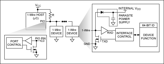
Overview Maxim's 1-Wire bus uses a very simple signaling protocol to implement half-duplex, bidirectional communication between the master / master controller and one or more slaves through a common data line (Figure 1). The power supply and data communication of the slave device are completed by this 1-Wire line. The power supply is implemented in the following manner: During the data transmission process, the internal capacitance of the slave is charged when the bus state is high, and the charge stored in the capacitor is used to power the device when the bus state is low. A typical 1-Wire master includes an open-drain I / O port and is pulled up to a 3V to 5V power supply through a resistor. Maxim can also provide a more complete host with a line driver. Using this intelligent communication technology, you can easily and efficiently add memory, authentication, and mixed-signal functions at any time.

Figure 1. In a 1-Wire master / slave configuration, all devices share a common data line.
64-bit serial number All 1-Wire systems have an important basic feature: each slave has a unique, unchangeable (ROM) 64-bit, factory laser engraved serial number (ID), this serial number is never Will repeat with another device. In addition to providing a unique electronic ID for the end product, the 64-bit ID code also allows the host to choose one of many slave devices attached to the same bus. Part of the 64-bit ID code is an 8-bit family code that is used to identify the device type and supported functions.
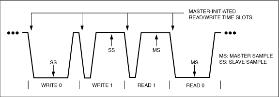
The data bit communication bus master initiates and controls all 1-Wire communications. As shown in Figure 2, the 1-Wire communication waveform is similar to pulse-width modulation because data is transmitted through wide pulses (logic 0) and narrow pulses (logic 1) during data bit transmission (or time slots). When the bus master sends out a "reset" pulse of a predetermined width, the communication process is started, and the entire bus system is synchronized by the pulse. All slaves respond to the reset pulse with a logic low "acknowledge" pulse. When writing data, the host first pulls the 1-Wire bus low to start a time slot, then keeps the bus low (wide pulse) to send a logic 0, or releases the bus (narrow pulse) to return the bus to a logic 1 state. When reading data, the host pulls down the bus in a narrow pulse and restarts a time slot. The slave can then extend the pulse by turning on the open-drain output and keeping the line low to return to logic 0; or keep the open-drain off state to allow the bus to recover and return to logic 1. Most 1-Wire devices support two data rates: 15kbps standard rate and 111kbps high-speed rate. The protocol is self-synchronizing and accepts long delays between data bits, thereby ensuring normal operation in an interrupted software environment.

Figure 2. This waveform example shows the write / read data bits initiated by the master and the sampling points of the slave and master.
The first step in device selection for 1-Wire communication is to select a slave for subsequent communication. In a system with only one slave, the slave selection process is extremely simple. In a multi-slave system, either all slaves are selected, or a specific slave is selected by a 64-bit ID code. The binary search algorithm (called the ROM-level command in the 1-Wire data sheet) "learns" and then selects the corresponding 64-bit IDs of all slave devices on the bus. After selecting a specific slave, the master issues commands related to the device and sends data to the slave, or reads slave data. At the same time, all other slaves ignore this communication process until the master sends out the next reset pulse.
Conclusion You can add memory, digital, analog, and mixed-signal functions to the 1-Wire communication system. The various devices with rich functions can completely solve the space-constrained interconnection restrictions and / or realize the value-added functions through unique device characteristics. 1-Wire products are available in standard IC packages, as well as Maxim's proprietary rugged stainless steel iButton package. Please visit the 1-Wire webpage for detailed information on products, packaging and software support.
Overview Maxim's 1-Wire bus uses a very simple signaling protocol to implement half-duplex, bidirectional communication between the master / master controller and one or more slaves through a common data line (Figure 1). The power supply and data communication of the slave device are completed by this 1-Wire line. The power supply is implemented in the following manner: During the data transmission process, the internal capacitance of the slave is charged when the bus state is high, and the charge stored in the capacitor is used to power the device when the bus state is low. A typical 1-Wire master includes an open-drain I / O port and is pulled up to a 3V to 5V power supply through a resistor. Maxim can also provide a more complete host with a line driver. Using this intelligent communication technology, you can easily and efficiently add memory, authentication, and mixed-signal functions at any time.

Figure 1. In a 1-Wire master / slave configuration, all devices share a common data line.
64-bit serial number All 1-Wire systems have an important basic feature: each slave has a unique, unchangeable (ROM) 64-bit, factory laser engraved serial number (ID), this serial number is never Will repeat with another device. In addition to providing a unique electronic ID for the end product, the 64-bit ID code also allows the host to choose one of many slave devices attached to the same bus. Part of the 64-bit ID code is an 8-bit family code that is used to identify the device type and supported functions.
The data bit communication bus master initiates and controls all 1-Wire communications. As shown in Figure 2, the 1-Wire communication waveform is similar to pulse-width modulation because data is transmitted through wide pulses (logic 0) and narrow pulses (logic 1) during data bit transmission (or time slots). When the bus master sends out a "reset" pulse of a predetermined width, the communication process is started, and the entire bus system is synchronized by the pulse. All slaves respond to the reset pulse with a logic low "acknowledge" pulse. When writing data, the host first pulls the 1-Wire bus low to start a time slot, then keeps the bus low (wide pulse) to send a logic 0, or releases the bus (narrow pulse) to return the bus to a logic 1 state. When reading data, the host pulls down the bus in a narrow pulse and restarts a time slot. The slave can then extend the pulse by turning on the open-drain output and keeping the line low to return to logic 0; or keep the open-drain off state to allow the bus to recover and return to logic 1. Most 1-Wire devices support two data rates: 15kbps standard rate and 111kbps high-speed rate. The protocol is self-synchronizing and accepts long delays between data bits, thereby ensuring normal operation in an interrupted software environment.

Figure 2. This waveform example shows the write / read data bits initiated by the master and the sampling points of the slave and master.
The first step in device selection for 1-Wire communication is to select a slave for subsequent communication. In a system with only one slave, the slave selection process is extremely simple. In a multi-slave system, either all slaves are selected, or a specific slave is selected by a 64-bit ID code. The binary search algorithm (called the ROM-level command in the 1-Wire data sheet) "learns" and then selects the corresponding 64-bit IDs of all slave devices on the bus. After selecting a specific slave, the master issues commands related to the device and sends data to the slave, or reads slave data. At the same time, all other slaves ignore this communication process until the master sends out the next reset pulse.
Conclusion You can add memory, digital, analog, and mixed-signal functions to the 1-Wire communication system. The various devices with rich functions can completely solve the space-constrained interconnection restrictions and / or realize the value-added functions through unique device characteristics. 1-Wire products are available in standard IC packages, as well as Maxim's proprietary rugged stainless steel iButton package. Please visit the 1-Wire webpage for detailed information on products, packaging and software support.
Porsche Dashcam,Dash Cam With G Sensor,Dash Cam With Loop Recording
SHENZHEN ROSOTO TECHNOLOGY CO., LTD. , https://www.rdtkdashcam.com