Abstract: Through the Internet, old computer equipment can be brought back to life. This application note explains how to use TINI® and re-use the old dot matrix printer with only one parallel port through the network. Using the same protocol conversion technology, many devices can be connected to the Internet.
Introduction The wife threw away only two holes in the socks and the slightly grassy shirt, which is nothing. But when she turned her target to the old dot matrix printer, I protested. She said disdainfully: "This thing hasn't been used for a long time, and it can't be connected to any computer." Like Frankenstein, I can't tolerate any idea of ​​discarding old computer equipment. The purpose is very clear: turn the printer into a treasure, or simply discard it. I decided to bring it back to life through the network, but fortunately a TINI (micro network interface) can be used to complete this work.
Connected Network TINI is an embedded network platform provided by Maxim. It is based on the company's DS80C390, DS80C400, DS80C410, and DS80C411 microcontrollers. These devices are enhanced 8051 controllers with features such as 24-bit addresses, hardware network controllers, multiple data pointers, dedicated hardware stacks, and high-speed operating modes.
The TINI platform supports TCP / IP network stacks (IPv4 and IPv6), memory management, process scheduling, and communication protocols such as I²C, SPI, and CAN. Through the common programming interface, 8051 assembly language, C or Java can be used to program TINI. C runtime can provide a Berkeley socket (socket interface), Java runtime environment supports Java 1.1.8 API kernel.
TINI has rich IO, simple network interface and multiple programming methods. It is a set of powerful protocol converters. This is exactly what is needed to save that old printer: TINI provides a network interface, and I decide how to allow TINI to communicate with the printer.
The core part of the hardware configuration system uses a TINI evaluation (EV) board. The evaluation board is based on the DS80C400 microcontroller and includes 1MB flash memory, 1MB RAM, and connectors for RS-232 and Ethernet communication. Although its memory configuration is compatible with the TINI Java operating environment, it can still be programmed in C and assembly language. This provides multiple options for printer interface prototyping and application implementation.
The printer model in question is Epson LX-800. From the perspective of carbon dating and thick dust, it is the product of the age of the adjacent vacuum tube and hula hoop. LX-800 is a 9-pin printer, where 9-pin refers to the number of pins in the print head, not the number of parallel signals driving the printer. Actually, 17 signals (excluding ground) are required to drive the printer. The common signals of the parallel interface of the PC printer and their arrangement in the 25-pin printer connector are shown in Figure 1.
Figure 1. 25-pin signal definition for parallel printer interface
The traditional 25-core Centronics printer cable is used to connect the TINI and the printer. First, it needs to match the connection shown in Figure 1. However, there is still a problem: the IO of the TINI board is not suitable for use as a wide parallel bus. There are only 8 or 9 general-purpose IO (GPIO) signals, about half the number of required signals. These GPIO signals are distributed in multiple different registers. Due to the need to write to multiple registers to set 8 output bits, this limitation of GPIO signals makes it simple to write to the printer's 8-bit data bus. Fortunately, the TINI socket board reserves pads and traces for adding CPLD (complex programmable logic device), which can greatly enhance TINI's IO performance. Once the CPLD is installed, only one plug for programming the CPLD (via the JTAG interface) and one plug that can access certain TINI pins are required.
CPLD configuration CPLD can be considered as programmable hardware. CPLD has a very flexible internal architecture that can implement many logical functions and state machines. The TINI socket board reserves space for the XILINX® CoolRunner®-II XC2C64 CPLD in a 100-pin VQFP package; it also supports other CoolRunner-II in the same package and pin configuration. This project uses a large-capacity device XC2C128 with the same pin configuration.
The CPLD is connected to the TINI system through the external memory bus of the DS80C400 microcontroller. The microcontroller only needs to read / write a specific address to access the CPLD:
read_from_cpld: mov dptr, # 0C00000h; CPLD address movx a, @dptr; The task of read from the device CPLD is more complicated. On the one hand, CPLD needs to correctly respond to TINI's external memory bus signals: when TINI writes CPLD, CPLD must read the bus value; when TINI reads CPLD, CPLD must provide the bus value. On the other hand, for printers, CPLD needs to read status signals (such as BSY) indicating the operation of the printer and provide output signals (such as 8-bit data bus and write strobe STR) to control the printer. Figure 2 shows the functional block diagram that CPLD needs to implement.
Figure 2. There must be an interface between the CPLD's own IO pins and the microcontroller's address bus.
There are four 8-bit registers in the CPLD, corresponding to the 32 I / O pins of the CPLD. When the register bit is set to 0, the corresponding output pin is driven low; when the register bit is set to 1, the output pin is floating. Therefore, when CPLD reads data through the I / O pin, the corresponding register bit should be set to 1, so that the pin will not be driven to any value.
All input signals in Figure 2 come from TINI's external memory bus. When TINI writes CPLD, the data bus is the 8-bit value that TINI will write. When TINI performs a read operation, CPLD drives the data bus based on the detected input value. However, since other devices may share the bus, the CPLD cannot drive the data bus every time the TINI requests a read operation (that is, each time the nPSEN signal is valid). If the CPLD always responds to read operations, TINI will read the wrong instructions or data and produce unpredictable system operations (ie, "produce errors"). Similarly, not all write operations are directed to CPLD, therefore, CPLD cannot always respond to every write operation of TINI (that is, each nWr signal is valid). Therefore, whether the read and write signals in FIG. 2 are valid is determined by the address line.
As long as address lines AH0 and AH1 (the 16th and 17th address lines of TINI) are 0, and the selected chip enable is valid (in this example, chip enable 6 is used), CPLD is activated. Since each chip enable of TINI corresponds to 2MB of space, the base address for accessing CPLD is 0xC00000 (2,097,152 × 6 = 12,582,912 = 0xC00000). It should be noted that when TINI and CPLD interfaces in this design, most of the address lines of TINI are not specified. For example, when the address lines A2 to A15 of TINI are any value, CPLD can still be activated. However, for convenience, the source code always uses addresses 0xC00000 to 0xC00003 to access the four 8-bit registers.
Write CPLD program in HDL (Hardware Description Language). It is developed using Xilinx WebPACK â„¢ and written in Verilog â„¢ hardware description language. The module definition is shown in Figure 2. It includes an independent 8-bit register module, multiplexer and decoder. Implement module and address decoding in the top-level module.
After CPLD is installed and programmed, before connecting to the printer, I also want to check which signals are used. So a small circuit board was built, connecting 4 groups of LEDs with 4 logical registers (IO7: 0, IO15: 8, IO23: 16 and IO31: 24), as shown in Figure 3. A small program was written in C to increase the value of the 4 groups of LEDs, and a pause was inserted in the middle to pass the visual verification of the operation process of the program. After making sure that the CPLD is programmed and connected correctly, you can connect to the printer. Figure 3 shows the flying lead connection between the TINI board and the 25-pin printer connector.
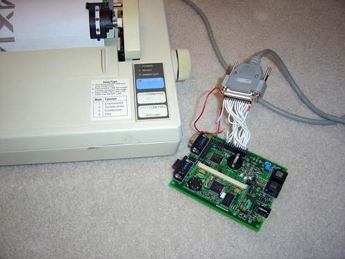
Figure 3. TINIs400 socket board connected to Epson printer
The ultimate goal of communication with the printer is to make the printer work normally without any special drivers or customer applications. Simply put, it is trying to use the built-in print driver and the Windows® print dialog box to make the old-style printers work. The final test step of this application is to print MS Word documents; if problems occur, Word will disclose some information. Although printing out MS Word documents is the ultimate goal, I still hope to use a more concise program to achieve this goal.
The first step is to try a simple application and send some ASCII characters to the printer without an Internet connection. This method can only play a debugging role. In theory, as long as it does not send command codes and other non-ASCII characters, the printer will print each character directly. It is hoped that this project, like all good engineering projects, can be printed smoothly and quickly, so that the network interface can be determined as soon as possible. Actually I was completely wrong.
Using Keil Software® µVision® 2 tool suite and the first printer application program was written in C language. According to the instructions of the Indispensable PC Hardware Book, it seems that the printer needs to be initialized and characters are written¹. The algorithm for writing characters is relatively simple: wait for BSY to become invalid. Set the output value on the data bus. Set the write strobe STR to valid. Wait for the ACK signal to confirm that the data has been received. Set write strobe STR to invalid. It can be cleared or repeated as needed. During the first step test, many delays are set in the algorithm, so that if there is a status signal error (polarity error, pin error, etc.), you should see some information about the write operation. Therefore, the first program writes approximately one character per second. Only one up-counter is written in this design, namely:
012345678901234567890123456789 ...
Download the program to TINI and run it. I immediately knew that the printer initialization procedure was working properly, because when I turned off and on again, I could hear the sound of the print head moving. However, after a few seconds nothing was printed. Reset the program and carefully check whether the connection is correct. Unfortunately, there is no time left to monitor the printer's status signal. Everything is normal, so I went back to the computer hardware guide to find the answer. After some research, the polarity of certain signals was discerned. For example, as far as the traditional PC interface is concerned, this signal is valid when BSY is 0, but in terms of hardware, it is actually high level. Modify the C program repeatedly, and change the polarity of different signals, but the printer still cannot work after initialization. I checked the program again to match the logic level to the printer signal level I imagined. After modifying the program and running it, the printer still did not respond.
After leaving for a while, I heard a harsh sound when the dot matrix printer printed a line of text. A recent look has printed a beautiful line of characters, but then the printer stopped. A principle suddenly came to mind: no matter whether the limit of 80 characters is reached or whether the end-of-line sequence is inserted into the data stream, the printer does not buffer until the end of the line. The working process of several printing operations proves this principle. You can now print a few lines of text.
The next day after implementing the LPD monitoring program, it was decided to connect the network to the printer interface. Simply put, it is to create a user application that directly receives data from the network and outputs it to the printer. The problem with this method is that if you want the printer to work with MS Word, you also need to write a Windows printer driver. This step can be achieved, but this is not my fun. The practice of writing a driver has been around for a long time, and I do n’t need to do more. I began to consider other options. I hope that I can achieve my goal without knowing all the details of the printer driver.
The ideal design should be a virtual parallel port. In other words, the virtual parallel port provides the same interface as the standard parallel port, but as far as the driver is concerned, it actually sends and receives data to TINI through the network. Virtual ports and protocol converters like this are general applications of TINI. According to this design idea, I have had some experience in implementing virtual serial ports. It seems that many applications directly write parallel registers of the PC, so it is difficult to determine how to implement this design idea. The next step is to review the existing agreement. According to a colleague ’s suggestion, I reviewed RFC 1179, the line printer monitoring program LPD) protocol².
LPD can just meet the needs. UNIX usually supports this network protocol, but it can also be used in Windows after simple configuration. When installing the driver, notify Windows to install a new local printer connected to the computer instead of telling it which existing port to use, thus creating a new LPR port. Here you can define the name of the machine running the LPD server (in this case, the IP address of TINI), and provide the name of the print queue. (There is only one print queue named 'crusty'. I think this name is very suitable for my printer.) Finally, tell the Windows printer model (the author's printer is Epson LX-800).
This setting has the advantage that the Windows printer driver can automatically process all data formats to print using the printer's original statement (Epson ESC / P). In this way, there is no need to understand the ESC / P language, nor to parse any data transmitted by the PC to TINI. In addition, it is very easy to implement a basic LPD server; call a small number of Java native methods to achieve access to the memory-mapped CPLD. The final actual code is about 400 lines, and the Java class file prepared for TINI is only 4kB. It should be noted that I did not implement the entire LPD protocol, only the partial protocol required to print one file at a time.
After printing, you can do three things to complete the design: print the Notepad file, print the MS Word file, or print a small GIF or JPG file if you still have n’t gotten enough. After some debugging of the LPD server, the Notepad file was successfully printed. Strangely enough, printing 2 lines of text sent about 5,000 bytes to TINI. In fact, this is because the Windows driver converts the entire file to an ESC / P command to send a bitmap image instead of simply sending ASCII characters. After printing the Notepad document, print the MS Word document instead.
There was a small problem when printing the MS Word document. In order to make the test file more interesting, different fonts are changed every two or three words, so that you have the opportunity to see some fonts that have never been seen before. When printing, there are many useless character graphics: the printer will skip a few lines, and then print out some strange ASCII graphic characters (some characters in the range of 0x80 to 0xFF), and continuously beep. Finally, some correct text was finally printed, but then there was a bunch of garbled characters. After several rounds of debugging, and tracking the ESC / P command sent to TINI, I decided to try to increase the delay for the escape character. This will run the printing program correctly, but it is very slow. After many trials, it was found that it was only necessary to increase the delay when the end-of-line character was encountered during printing. This situation rarely occurs, so there is no delay in actual printing.
Due to some difficulties in printing MS Word documents, it was almost impossible to conclude that it was impossible to print GIF files, but this was not the case. Only one problem was encountered when printing: the size of the GIF file after conversion to the ESC / P command was greater than 64k, and 64k is the maximum dynamic buffer size supported by the TINI version used. However, TINI supports a file system without this limitation, so you can store the received data in a file instead of in a dynamic memory buffer. Once the above method is used, the graphics file can be printed smoothly, and it is only limited by the RAM size in TINI.
Rescue other (outdated) equipment The method described in this article has given birth to an old dot matrix printer. Among them, TINI played a key role. Its easy-to-program stack provides an excellent choice for re-enabling older devices over the network. The benefits of TINI are not limited to connecting parallel interface devices to the network; it also supports CAN, SPI, I²C, RS-232, 1-Wire, and many other communication buses, so TINI is an excellent way to bridge various old devices to the network select. The software supports network protocols such as DHCP, HTTP, FTP, Telnet, and DNS, and provides multiple methods for accessing old devices (such as the webpage method). When you need more convenient access to expensive, outdated equipment, TINI is ideal. (Buying a new dot-matrix printer currently costs about $ 400!) Therefore, don't throw away old objects. TINI can be very useful.
Introduction The wife threw away only two holes in the socks and the slightly grassy shirt, which is nothing. But when she turned her target to the old dot matrix printer, I protested. She said disdainfully: "This thing hasn't been used for a long time, and it can't be connected to any computer." Like Frankenstein, I can't tolerate any idea of ​​discarding old computer equipment. The purpose is very clear: turn the printer into a treasure, or simply discard it. I decided to bring it back to life through the network, but fortunately a TINI (micro network interface) can be used to complete this work.
Connected Network TINI is an embedded network platform provided by Maxim. It is based on the company's DS80C390, DS80C400, DS80C410, and DS80C411 microcontrollers. These devices are enhanced 8051 controllers with features such as 24-bit addresses, hardware network controllers, multiple data pointers, dedicated hardware stacks, and high-speed operating modes.
The TINI platform supports TCP / IP network stacks (IPv4 and IPv6), memory management, process scheduling, and communication protocols such as I²C, SPI, and CAN. Through the common programming interface, 8051 assembly language, C or Java can be used to program TINI. C runtime can provide a Berkeley socket (socket interface), Java runtime environment supports Java 1.1.8 API kernel.
TINI has rich IO, simple network interface and multiple programming methods. It is a set of powerful protocol converters. This is exactly what is needed to save that old printer: TINI provides a network interface, and I decide how to allow TINI to communicate with the printer.
The core part of the hardware configuration system uses a TINI evaluation (EV) board. The evaluation board is based on the DS80C400 microcontroller and includes 1MB flash memory, 1MB RAM, and connectors for RS-232 and Ethernet communication. Although its memory configuration is compatible with the TINI Java operating environment, it can still be programmed in C and assembly language. This provides multiple options for printer interface prototyping and application implementation.
The printer model in question is Epson LX-800. From the perspective of carbon dating and thick dust, it is the product of the age of the adjacent vacuum tube and hula hoop. LX-800 is a 9-pin printer, where 9-pin refers to the number of pins in the print head, not the number of parallel signals driving the printer. Actually, 17 signals (excluding ground) are required to drive the printer. The common signals of the parallel interface of the PC printer and their arrangement in the 25-pin printer connector are shown in Figure 1.
Figure 1. 25-pin signal definition for parallel printer interface
The traditional 25-core Centronics printer cable is used to connect the TINI and the printer. First, it needs to match the connection shown in Figure 1. However, there is still a problem: the IO of the TINI board is not suitable for use as a wide parallel bus. There are only 8 or 9 general-purpose IO (GPIO) signals, about half the number of required signals. These GPIO signals are distributed in multiple different registers. Due to the need to write to multiple registers to set 8 output bits, this limitation of GPIO signals makes it simple to write to the printer's 8-bit data bus. Fortunately, the TINI socket board reserves pads and traces for adding CPLD (complex programmable logic device), which can greatly enhance TINI's IO performance. Once the CPLD is installed, only one plug for programming the CPLD (via the JTAG interface) and one plug that can access certain TINI pins are required.
CPLD configuration CPLD can be considered as programmable hardware. CPLD has a very flexible internal architecture that can implement many logical functions and state machines. The TINI socket board reserves space for the XILINX® CoolRunner®-II XC2C64 CPLD in a 100-pin VQFP package; it also supports other CoolRunner-II in the same package and pin configuration. This project uses a large-capacity device XC2C128 with the same pin configuration.
The CPLD is connected to the TINI system through the external memory bus of the DS80C400 microcontroller. The microcontroller only needs to read / write a specific address to access the CPLD:
read_from_cpld: mov dptr, # 0C00000h; CPLD address movx a, @dptr; The task of read from the device CPLD is more complicated. On the one hand, CPLD needs to correctly respond to TINI's external memory bus signals: when TINI writes CPLD, CPLD must read the bus value; when TINI reads CPLD, CPLD must provide the bus value. On the other hand, for printers, CPLD needs to read status signals (such as BSY) indicating the operation of the printer and provide output signals (such as 8-bit data bus and write strobe STR) to control the printer. Figure 2 shows the functional block diagram that CPLD needs to implement.
Figure 2. There must be an interface between the CPLD's own IO pins and the microcontroller's address bus.
There are four 8-bit registers in the CPLD, corresponding to the 32 I / O pins of the CPLD. When the register bit is set to 0, the corresponding output pin is driven low; when the register bit is set to 1, the output pin is floating. Therefore, when CPLD reads data through the I / O pin, the corresponding register bit should be set to 1, so that the pin will not be driven to any value.
All input signals in Figure 2 come from TINI's external memory bus. When TINI writes CPLD, the data bus is the 8-bit value that TINI will write. When TINI performs a read operation, CPLD drives the data bus based on the detected input value. However, since other devices may share the bus, the CPLD cannot drive the data bus every time the TINI requests a read operation (that is, each time the nPSEN signal is valid). If the CPLD always responds to read operations, TINI will read the wrong instructions or data and produce unpredictable system operations (ie, "produce errors"). Similarly, not all write operations are directed to CPLD, therefore, CPLD cannot always respond to every write operation of TINI (that is, each nWr signal is valid). Therefore, whether the read and write signals in FIG. 2 are valid is determined by the address line.
As long as address lines AH0 and AH1 (the 16th and 17th address lines of TINI) are 0, and the selected chip enable is valid (in this example, chip enable 6 is used), CPLD is activated. Since each chip enable of TINI corresponds to 2MB of space, the base address for accessing CPLD is 0xC00000 (2,097,152 × 6 = 12,582,912 = 0xC00000). It should be noted that when TINI and CPLD interfaces in this design, most of the address lines of TINI are not specified. For example, when the address lines A2 to A15 of TINI are any value, CPLD can still be activated. However, for convenience, the source code always uses addresses 0xC00000 to 0xC00003 to access the four 8-bit registers.
Write CPLD program in HDL (Hardware Description Language). It is developed using Xilinx WebPACK â„¢ and written in Verilog â„¢ hardware description language. The module definition is shown in Figure 2. It includes an independent 8-bit register module, multiplexer and decoder. Implement module and address decoding in the top-level module.
After CPLD is installed and programmed, before connecting to the printer, I also want to check which signals are used. So a small circuit board was built, connecting 4 groups of LEDs with 4 logical registers (IO7: 0, IO15: 8, IO23: 16 and IO31: 24), as shown in Figure 3. A small program was written in C to increase the value of the 4 groups of LEDs, and a pause was inserted in the middle to pass the visual verification of the operation process of the program. After making sure that the CPLD is programmed and connected correctly, you can connect to the printer. Figure 3 shows the flying lead connection between the TINI board and the 25-pin printer connector.
Figure 3. TINIs400 socket board connected to Epson printer
The ultimate goal of communication with the printer is to make the printer work normally without any special drivers or customer applications. Simply put, it is trying to use the built-in print driver and the Windows® print dialog box to make the old-style printers work. The final test step of this application is to print MS Word documents; if problems occur, Word will disclose some information. Although printing out MS Word documents is the ultimate goal, I still hope to use a more concise program to achieve this goal.
The first step is to try a simple application and send some ASCII characters to the printer without an Internet connection. This method can only play a debugging role. In theory, as long as it does not send command codes and other non-ASCII characters, the printer will print each character directly. It is hoped that this project, like all good engineering projects, can be printed smoothly and quickly, so that the network interface can be determined as soon as possible. Actually I was completely wrong.
Using Keil Software® µVision® 2 tool suite and the first printer application program was written in C language. According to the instructions of the Indispensable PC Hardware Book, it seems that the printer needs to be initialized and characters are written¹. The algorithm for writing characters is relatively simple: wait for BSY to become invalid. Set the output value on the data bus. Set the write strobe STR to valid. Wait for the ACK signal to confirm that the data has been received. Set write strobe STR to invalid. It can be cleared or repeated as needed. During the first step test, many delays are set in the algorithm, so that if there is a status signal error (polarity error, pin error, etc.), you should see some information about the write operation. Therefore, the first program writes approximately one character per second. Only one up-counter is written in this design, namely:
012345678901234567890123456789 ...
Download the program to TINI and run it. I immediately knew that the printer initialization procedure was working properly, because when I turned off and on again, I could hear the sound of the print head moving. However, after a few seconds nothing was printed. Reset the program and carefully check whether the connection is correct. Unfortunately, there is no time left to monitor the printer's status signal. Everything is normal, so I went back to the computer hardware guide to find the answer. After some research, the polarity of certain signals was discerned. For example, as far as the traditional PC interface is concerned, this signal is valid when BSY is 0, but in terms of hardware, it is actually high level. Modify the C program repeatedly, and change the polarity of different signals, but the printer still cannot work after initialization. I checked the program again to match the logic level to the printer signal level I imagined. After modifying the program and running it, the printer still did not respond.
After leaving for a while, I heard a harsh sound when the dot matrix printer printed a line of text. A recent look has printed a beautiful line of characters, but then the printer stopped. A principle suddenly came to mind: no matter whether the limit of 80 characters is reached or whether the end-of-line sequence is inserted into the data stream, the printer does not buffer until the end of the line. The working process of several printing operations proves this principle. You can now print a few lines of text.
The next day after implementing the LPD monitoring program, it was decided to connect the network to the printer interface. Simply put, it is to create a user application that directly receives data from the network and outputs it to the printer. The problem with this method is that if you want the printer to work with MS Word, you also need to write a Windows printer driver. This step can be achieved, but this is not my fun. The practice of writing a driver has been around for a long time, and I do n’t need to do more. I began to consider other options. I hope that I can achieve my goal without knowing all the details of the printer driver.
The ideal design should be a virtual parallel port. In other words, the virtual parallel port provides the same interface as the standard parallel port, but as far as the driver is concerned, it actually sends and receives data to TINI through the network. Virtual ports and protocol converters like this are general applications of TINI. According to this design idea, I have had some experience in implementing virtual serial ports. It seems that many applications directly write parallel registers of the PC, so it is difficult to determine how to implement this design idea. The next step is to review the existing agreement. According to a colleague ’s suggestion, I reviewed RFC 1179, the line printer monitoring program LPD) protocol².
LPD can just meet the needs. UNIX usually supports this network protocol, but it can also be used in Windows after simple configuration. When installing the driver, notify Windows to install a new local printer connected to the computer instead of telling it which existing port to use, thus creating a new LPR port. Here you can define the name of the machine running the LPD server (in this case, the IP address of TINI), and provide the name of the print queue. (There is only one print queue named 'crusty'. I think this name is very suitable for my printer.) Finally, tell the Windows printer model (the author's printer is Epson LX-800).
This setting has the advantage that the Windows printer driver can automatically process all data formats to print using the printer's original statement (Epson ESC / P). In this way, there is no need to understand the ESC / P language, nor to parse any data transmitted by the PC to TINI. In addition, it is very easy to implement a basic LPD server; call a small number of Java native methods to achieve access to the memory-mapped CPLD. The final actual code is about 400 lines, and the Java class file prepared for TINI is only 4kB. It should be noted that I did not implement the entire LPD protocol, only the partial protocol required to print one file at a time.
After printing, you can do three things to complete the design: print the Notepad file, print the MS Word file, or print a small GIF or JPG file if you still have n’t gotten enough. After some debugging of the LPD server, the Notepad file was successfully printed. Strangely enough, printing 2 lines of text sent about 5,000 bytes to TINI. In fact, this is because the Windows driver converts the entire file to an ESC / P command to send a bitmap image instead of simply sending ASCII characters. After printing the Notepad document, print the MS Word document instead.
There was a small problem when printing the MS Word document. In order to make the test file more interesting, different fonts are changed every two or three words, so that you have the opportunity to see some fonts that have never been seen before. When printing, there are many useless character graphics: the printer will skip a few lines, and then print out some strange ASCII graphic characters (some characters in the range of 0x80 to 0xFF), and continuously beep. Finally, some correct text was finally printed, but then there was a bunch of garbled characters. After several rounds of debugging, and tracking the ESC / P command sent to TINI, I decided to try to increase the delay for the escape character. This will run the printing program correctly, but it is very slow. After many trials, it was found that it was only necessary to increase the delay when the end-of-line character was encountered during printing. This situation rarely occurs, so there is no delay in actual printing.
Due to some difficulties in printing MS Word documents, it was almost impossible to conclude that it was impossible to print GIF files, but this was not the case. Only one problem was encountered when printing: the size of the GIF file after conversion to the ESC / P command was greater than 64k, and 64k is the maximum dynamic buffer size supported by the TINI version used. However, TINI supports a file system without this limitation, so you can store the received data in a file instead of in a dynamic memory buffer. Once the above method is used, the graphics file can be printed smoothly, and it is only limited by the RAM size in TINI.
Rescue other (outdated) equipment The method described in this article has given birth to an old dot matrix printer. Among them, TINI played a key role. Its easy-to-program stack provides an excellent choice for re-enabling older devices over the network. The benefits of TINI are not limited to connecting parallel interface devices to the network; it also supports CAN, SPI, I²C, RS-232, 1-Wire, and many other communication buses, so TINI is an excellent way to bridge various old devices to the network select. The software supports network protocols such as DHCP, HTTP, FTP, Telnet, and DNS, and provides multiple methods for accessing old devices (such as the webpage method). When you need more convenient access to expensive, outdated equipment, TINI is ideal. (Buying a new dot-matrix printer currently costs about $ 400!) Therefore, don't throw away old objects. TINI can be very useful.
3.96Mm Ribbon Connector,Single Row Connector,Pc Board Connector,Pc Board Power Connector
YUEQING WEIMAI ELECTRONICS CO.,LTD , https://www.weimaicarconn.com