1 Introduction
In the measurement of electricity, voltage, current and frequency are the most basic three measurements, and the voltage measurement is the most common. Now the digital multimeter used by students can measure a variety of power, and has a certain precision and is easy to use. In order to let students better understand the working principle of digital voltmeters and stimulate their interest in MCU courses, this paper starts with software and hardware design, proteus simulation, production of real objects, error analysis, and explains how digital voltmeter works. , data processing method, digital signal software filtering principle.
2. Hardware design
The hardware circuit design consists of four parts: a/d conversion circuit, at89c51 single-chip system, led display system, and measurement voltage input circuit. The hardware circuit design block diagram is shown as in Fig. 1. The overall design block diagram is as follows:
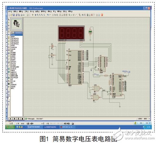
The working principle of this circuit is: +5v analog voltage signal is divided by the in0 channel of adc08008 after being divided by the varistor vr1 (due to the in0 channel used, so adda, addb, addc are connected to low level), after analog/digital conversion The corresponding digital quantity is transmitted to the p0 port of the at89c51 chip through its output channel d0-d7, and the at89c51 is responsible for processing the received digital quantity through the data, and generating the correct 7-segment digital tube display segment code to be transmitted to the four-digit led. At the same time, it also controls the digital tube to turn on and off through its four-bit i/o port p2.0, p2.1, p2.2, p2.3.
The hardware circuit of the simple digital DC voltmeter has been designed, you can select the corresponding chip and components, use the proteus software to draw out the principle of the hardware, and carefully check and modify until a complete hardware schematic is formed. However, in order to truly realize the function of measuring and displaying the voltage of the circuit, it is necessary to have corresponding software to meet the design requirements.
3. Software design
According to the division principle of the module, the program is divided into an initialization module, an a/d conversion subroutine and a display subroutine, and the three program modules constitute the main program of the whole system software, as shown in FIG. 2 .
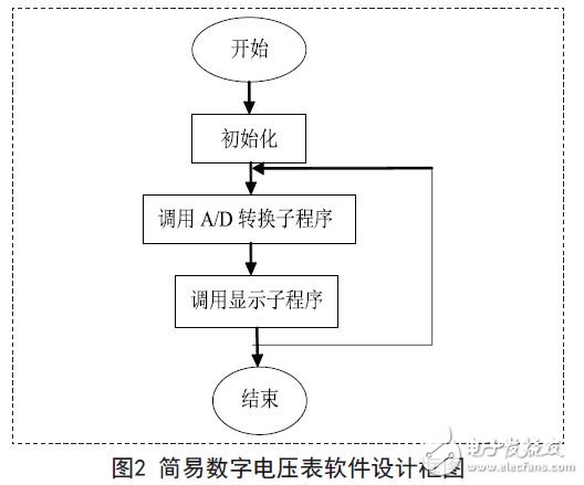
The core of the whole program design is to process the data of a/d conversion, including digital filtering processing and processing of data decimal places. The a/d conversion subroutine is used to control the acquisition and measurement of the input module voltage signal, and store the corresponding value in the corresponding memory unit.
The display subroutine uses dynamic scanning to realize the numerical display of the four-digit digital tube. When the dynamic scanning display mode is adopted, the LED display should be relatively uniform and have sufficient brightness, and an appropriate scanning frequency needs to be set, when the scanning frequency is about 70hz. When the display effect is better, the LED can be dynamically scanned once at intervals of 10MS, and the display time of each LED is 1MS.
Deep Cycle GEL VRLA Batteries,deep cycle battery,gel battery,valve regulated lead acid vrla,valve regulated lead acid,golf buggy batteries
EMoreShare International Trade (Suzhou) Co., Ltd , https://www.emoresharesystem.com