Turnout is a kind of line connection equipment that makes the rolling stock transfer from one track to another, and it is also one of the weak links in the track. It is usually laid at a large number of stations and marshalling stations. With the turnout, we can give full play to the route's ability to pass. Even if it is a single-lane railway, laying a turnout and building a fork that is longer than the length of the train, it is possible to open the train. The turnout plays an important role in the railway line.
With the rapid development of the national economy, high-speed and heavy-load have become the development trend of China's railways. The exchange rails are widely used due to their large internal resistance, long transmission distance, no maintenance of the motor, and saving of cables. The associated troubleshooting of the AC switch circuit is also emerging as a new topic. The fault processing of the AC turn-off circuit is divided into a turn-on start-up circuit and a turn-based turn-on circuit. This paper describes the fault handling of the turn-off circuit.

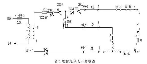
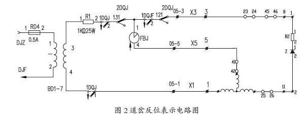
1, the road sign that circuit (Figure 1, Figure 2)
2. The switch indicates the working principle of the circuit and the specific circuit path
1) The reversed bit represents the circuit structure and basic working principle
The reversed bit indicates that the circuit is mainly composed of two parallel branches: one branch route relay contact, internal switch point relay, diode combination, and motor coil cascade connection. We call it a diode branch; one branch route single representation Contacts, relays, and motor coils are connected in series and we call them relay branches. The relationship between them is that the rectifier action of the diode branch provides the half-wave rectification power for the relay in the relay branch; the diode branch and the relay branch complete the check of the integrity of the stator coil of the switch motor.
2) Positioning indicates circuit path
(1) Positioning relay branch circuit path
BD1-7 coil 4-1DQJ13-11-05-1 (x1 function line) a cable box 1 # terminal a motor coil l a motor coil 3 a switch automatic switch 12-11 a cable box 4 # terminal A 05-4 (X4 function line) a DBJ1-4-2DQJ132-131 - 1DQJ21-23 - R1 (2-1) a coil BD1-7.
(2) Positioning diode branch circuit path
BD1-7 Coil 4-1 DQJ13-11-05-1 (x1 function line) a cable box 1 # terminal a motor coil 1 a motor coil 2 a switch automatic switch 35-36 a cable box 12 # terminal A R2 a diode tube a cable box 7 # terminal a 16-15-34-33 ~ cable box 2 # terminal a 05-2 (X2 function line) 2DQJ112-111-1DQJF11-13-2DQJ132-131-1DQJ21-23 Coil 3 of R1(2-1)-BD1-7.
3) Reverse bit indicates circuit path
(1) Reverse relay branch path
BD1-7 coil 4-1DQJ13-11-05-1 (x1 function line) a cable box 1# terminal a motor coil l a motor coil 3 a switching machine automatic shutter 42-41 a cable box 5 # terminal A 05-5 (X5 function line) a FBJ4-1-2DQJ133-131-1DQJ21-23 a R1 (2-1) a BD1-7 coil 3.
(2) Reverse bit diode branch path
BD1-7 coil 4-1DQJ13-11-05-1 (x1 function line) a cable box 1 # terminal a motor coil 1 a motor coil 2 a switch automatic switch 25-26 a cable box 11} A terminal of a diode-R2 cable box 8# terminal 46-45-24-23 a cable box 3# terminal O5-3 (x3 function line) a 2DOJ123-121-1DQJF21-23- 2DQJ133-131- 1DQJ21 - 23 coil 3 of R1 (2-1) BD1-7.
4) Indicates circuit summary
Positioning indicates that the circuit uses XI, X2 and X4, X1 and X2 constitute a diode branch, X2 and X4 constitute a relay branch, and the counter bit indicates that the circuit uses x1, X3 and X5, and X1 and X3 constitute a diode branch. X3, X5
Second, that circuit failure _ voltage data analysis1, measurement, analysis of the agreed conditions
According to the structure of the indicated circuit, we use the problem solving concept of electrical power theory to analyze. The failure of the circuit is mainly caused by the failure of these two circuits. Next, we use the X1, X2, X3, X4, and X5 function test terminals as voltage measurement points. We use a full-wave or digital multimeter to perform voltage tests. We use the normal representation of the circuit to represent the voltage and the fault indicates the voltage data for analysis. The method of judging the condition of the circuit failure. Test point: The branch point of the parallel branch is X1 and X4, that is, the DBJ line pack 4 is 1 and the diode branch voltage is measured on x1; the DBJ line pack 4 is the 1-end-x4 measurement relay branch voltage.
2, normal indicates voltage data
Diode branch voltage AC voltage is about 60V, the relay branch AC voltage is about 60V, and the DC voltage of both branches is about 20V-23V.
3, broken line failure analysis
1) The number of open circuit fault diodes
According to causes and analysis of the diode branch voltage AC voltage 110V, relay branch AC voltage 110V, no DC voltage. Analysis of voltage data: One of the two branches of the parallel load is open circuit, which will inevitably lead to an increase in the total load resistance and a rise in voltage; the fixed-table relay (polar relay) acts as a load and is equivalent to an open circuit state for the alternating current.
The open circuit of the diode branch will actually show that the two parallel branches of the circuit are all open, and the fault voltage will be 1IOV, and there will be no DC voltage.
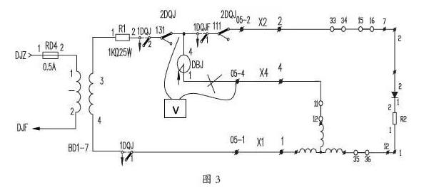
2) The number of voltages of the relay branch open circuit fault
According to the cause analysis, the voltage of the diode branch voltage is about 75V, the relay branch AC voltage is 75V or 0V, and the DC voltage is about 38V. Principle analysis: One of the two branches of the shunt load will inevitably lead to an increase in the total load resistance, so the voltage of the diode branch voltage will increase (from 60V to 75V). Why does the relay branch voltage appear? 0V or 75V situation? We analyze the principle of electrical power for the simplified circuit: the branch point of the relay branch is in the indoor direction at the x4 test point, then 75V will be measured in the DBJ package 4 and 05-4, and the measured voltage is actually X2. The voltage on X1. As shown in Figure 3.
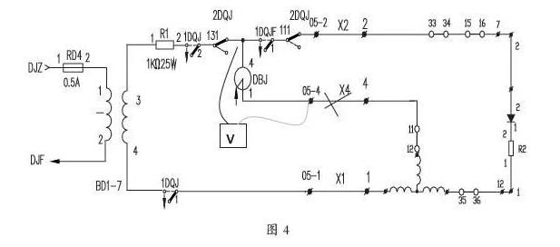
The branch point of the relay branch is in the outdoor direction at the test point (switching direction), then 0V voltage will be measured in the DBJ package 4 and 05-4, and the measured voltage is actually between X2 and x4. The voltage of a single lead connected to X2 is 0V, as shown in Figure 4.
4ã€The conclusion of the regularity of the disconnection of the relay branch
1) The relay branch is disconnected and the AC voltage between X1 and X2 rises to about 75V.
2) Test the terminal voltage of X2 and X4 function tests further. If the voltage between the X2 and X4 function test terminals is 75V, then it can be determined that the X4NI] test terminal is disconnected from the room; if the X2 and X4 function test terminals are connected, If the measured voltage is 0V, then it is determined that the X4 test end is disconnected in the direction of the outside (switching direction). Specific locations of X4 breaks can be determined by testing the voltage between the X2, X4 functional test terminals at different locations (eg, combination side, breakout board, cable box, etc.). The processing interface is: there is voltage, the indoor direction X4 is disconnected, the voltageless outdoor direction X4 is disconnected, and the minimum unit of disconnection and constant crossing is the fault line segment.
3) X4 branch contains the path: DBJ4-1 a combination side 05-4 a cable-disc board a host cable box D4 terminal an automatic switch l1-12 a motor coil.
4) Paths contained in X5 branch: FBJ1-4 A combination side O5-5 A cable tray A cable path A host cable box D5 Terminal An automatic switch 4l A 42 Motor coil.
5, short circuit fault analysis
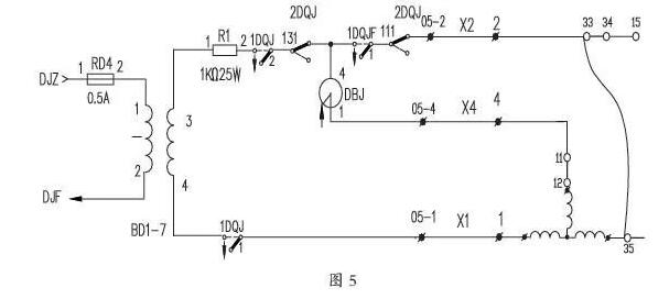
1) Diode branch short circuit positioning circuit diagram (Figure 5)
2) Relay branch short circuit positioning circuit diagram (Figure 6)
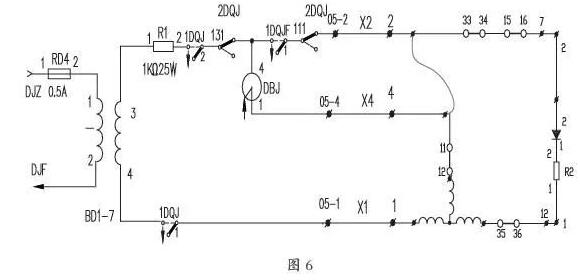
3) Short-circuit fault analysis
No matter what kind of short circuit, the circuit structure shown is basically similar. The voltages of the X1 and X2 function lines are measured only by the voltage of one stator coil. The short circuit fault voltage measured at the Xl, X2 functional test terminal is about 18V. By simplifying the circuit, we can also find that when the fault voltage is 18V, regardless of whether the relay branch is short-circuited or the diode branch is short-circuited, the positioning status is related to X2; the reverse status is related to X3. Short-circuit fault handling can be achieved by dropping the X2 or X3 path.
Third, the conclusionInterchanges indicate that circuit faults are ever-changing in the field. Only the understanding of circuit principles and troubleshooting methods can be applied flexibly. The above are some points of experience that the writer has been summing up and summing up in the field work in these years. The deficiencies, please everyone criticize and correct me. In the future construction and daily maintenance work, I still need to further explore and improve it, so that it can be an easy-to-understand, fast-acting maintenance guide and provide a good operating environment for the safe transportation of railways.
ZGAR Vape Pods 5.0
ZGAR electronic cigarette uses high-tech R&D, food grade disposable pod device and high-quality raw material. All package designs are Original IP. Our designer team is from Hong Kong. We have very high requirements for product quality, flavors taste and packaging design. The E-liquid is imported, materials are food grade, and assembly plant is medical-grade dust-free workshops.
From production to packaging, the whole system of tracking, efficient and orderly process, achieving daily efficient output. WEIKA pays attention to the details of each process control. The first class dust-free production workshop has passed the GMP food and drug production standard certification, ensuring quality and safety. We choose the products with a traceability system, which can not only effectively track and trace all kinds of data, but also ensure good product quality.
We offer best price, high quality Pods, Pods Touch Screen, Empty Pod System, Pod Vape, Disposable Pod device, E-cigar, Vape Pods to all over the world.
Much Better Vaping Experience!


ZGAR Vape 5.0 Pods,ZGAR Vape Pods 5.0,ZGAR Vape Pods 5.0 Pod System Vape,ZGAR Vape Pods 5.0 Disposable Pod Vape Systems
Zgar International (M) SDN BHD , https://www.zgarpods.com